SPECIAL REPORT: Level 6 multilateral numbers increase
Level 6 multilateral-junction well completions have started gaining acceptance in the petroleum industry. These completions offer reduced installation risk, faster installation times, and greater flexibility.
The TAML (Technology Advancement of Multilaterals) industry group defines a Level 6 multilateral junction as a system that provides hydraulic isolation of the junction area with casing rather than through the use of straddle completion equipment.
To date, the industry has installed 18 Level 6 junctions around the world in a variety of surface and reservoir conditions that include offshore, land; deep and shallow formations; and in high and low-pressure reservoirs.
Evolution of multilaterals
The industry installed the first and simplest multilateral wells in the 1950s; however, only in the last 5-6 years have these systems offered mechanical or hydraulic support at the junction.
Operators have installed several hundred mechanical support systems in the last 5 years because these are quick and easy to install with today's technology.
Construction of a multilateral well with hydraulic isolation is more challenging. Initially, the process involved creating a casing exit in the main casing bore through which the lateral is drilled and completed. In the next step, the junction area is isolated hydraulically by completion "straddle" assemblies designed to seal off in the main and lateral casing strings. But the multiple trips required for placing the tools and achieving hydraulic integrity increases both the risk and cost of these operations.
The straddle assemblies within the junction limit the completion options possible As a result, these types of multilateral installations have only found limited acceptance.
Current Level 6 multilateral systems include manufactured casing junctions run in hole as a single component. These junctions basically are specialized casing joints with two casing legs extending below the manufactured junction assembly. This simple concept provides advantages in terms of downhole installation and flexibility.
The junctions eliminate the debris created and needed to be removed when installing a Level 5 system in which the liner lap is washed over, creating a flush junction in the casing ID.
Level 6 junctions do not depend on the cement job quality at the junction. Also this junction's integrity, unlike Level 5 junctions, allows the laterals to be constructed from the top down or even later in the life of the well. Level 5 installations, on the other hand, require exiting from the casing and having at least part of the build section or lateral drilled and completed immediately.
Level 6 junctions also provide a hydraulic seal, eliminating the need for multilateral-specific completion sealing systems. As a result, the completion can include a large range of conventional flow control and completion accessories as part of the multilateral system.
Trilateral Level 6
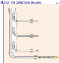
Marathon Oil Co installed one type of Level 6 completion in a well in the Carter-Knox in Oklahoma. This trilateral Level 6 completion included a Baker Oil Tools' Stackable Splitter that allows multiple junctions to be run as part of a single casing string (Fig. 1).

The Carter-Knox field is a mature field. Production started in the 1930s from shallow zones and in 1950s from deeper zones. As a result, the field has many old wells and pipelines that leave little room for new well locations. Also a thrust fault makes drilling problematic and time-cost intensive.
By using a multilateral approach, Marathon minimized surface locations and required only one borehole through the fault zone. This approach also allowed Marathon to tap multiple reservoirs, which because of their compartmentalization are difficult to adequately exploit with a conventional well.
With three zones targeted, this project included two separate Level 6 junctions run downhole as part of the casing string that was run through a 13 3/8-in. casing string. The junctions were set at 7,600 and 7,900 ft and each junction had 5 1/2-in. legs.
The work did not require additional trips to place the junctions. Straddle wiper assemblies across each junction made it possible to cement down casing with conventional cementing techniques and equipment, without contaminating the junction assembly.
A selective diverter system helped guide the 4 3/4-in. drilling assemblies into each lateral leg to initiate drilling the laterals. These diverters land in a nipple profile portion of the junction and provide fullbore access to the lateral. Additionally, the diverters contain a packing element assembly and therefore provide pressure isolation of the lower zones during construction of the upper lateral.
After each lateral leg was drilled, the procedure including running and cementing liners in each lateral. The liner was hung off in each junction leg with standard hanger assemblies and running tools.
After cementing the liners, a workover rig replaced the drilling rig. This change in rigs saved cost and would not have been possible with earlier Level 5 multilateral installations.
The completion work included perforating each zone with tubing-conveyed guns and fracing each zone with up to 120,000 lb of proppant and treating pressures up to 7,500 psi. The high-pressure rating of the junctions and the pressure isolation of the lower zones provided by the diverters allowed the frac operations to be conducted down casing rather than through a treating string. This saved costs and improved stimulation results.
After all zones had been treated, the well began commingled production from all completed zones.
This type of completion allows re-entry into any zone if additional stimulation or flow shut-off jobs are needed in the future.
Dual production Level 6
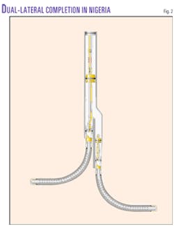
In Nigeria, Shell Petroleum Development Co. Ltd. (SPDC) installed another type of Level 6 multilaterals in sandstone reservoirs in both Imo River and Agbada fields. These multilaterals used Baker Oil Tools' Deepset Splitter junction that is similar to the Stackable Splitter discussed previously (Fig. 2).
The Imo River field, discovered in 1959, has had more than 60 wells drilled. SPDC decided to install multilaterals in two new wells primarily to reduce costs. By reducing surface location requirements, it minimized equipment and project time. The multilaterals also lessened the environmental impact in sensitive surface locations.
SPDC's quantitative risk analysis (QRA) showed that Level 6 multilateral options offered minimal installation and deployment risk compared to other possible multilateral options.
The two T-installations are Level 6 junctions that offer maximum hole length capability, high pressure ratings, and isolated dual production while maintaining simple, low-risk installation techniques.
As with the other Level 6 junction versions, the splitter in the Nigerian applications consisted of a specialized casing assembly with two separate casing legs extending below the junction.
In one well, the junction, run in as part of the intermediate casing string, was set vertically at 4,900 ft. The procedure included making an orientation run to determine the alignment of the two splitter legs prior to hanging off the assembly in the wellhead. In this well, the alignment proved nearly optimal and the rig did not have to further rotate the junction casing assembly.
In drilling this offshore well, a combination drilling riser and diverter system provided selective access to each of the two junction legs during the cementing, drilling, and completion processes. The selective access features of this riser system also protected the junction during cementing operations and ensured sufficient annular velocity to effectively remove the cuttings to surface during drilling operations.
The riser system had a riser tension hanger that allowed tensioning the riser (thereby preventing fatigue failure), a 9 5/8 and 7 5/8-in. tapered casing string for fluid transfer, and a riser diverter that latched into the top of the multilateral junction and directed bottomhole assemblies to the correct lateral wellbore leg.
The riser essentially allowed the well to be treated as though it was a standard, conventional well during the subsequent operations.
The procedure for cementing the junction and casing assembly in place used a standard drill pipe slick stinger that required the riser assembly to be stabbed into the first leg and hung off 180 ft below the blowout preventer stack. The job used a standard Class G, 3,000-psi compressive strength cement followed by a pump-down plug. The slurry was pumped and the cementing assembly was retrieved without problems.
With the junction cemented in place and the riser still stabbed into the first leg, the rig drilled the build section from 4,090 to 7,572 ft measured depth (MD) with a conventional 4 3/4-in. motor and measurement-while-drilling (MWD) assembly and a 7-in. steerable ream-while-drilling (SRWD) bit.
Drilling plans called for a 10°/100-ft build rate in order to reach the liner setting depth target at a 90° inclination. In actuality, however, the SRWD and motor combination yielded only 60% of the calculated dogleg.
The job cased the build section with a 5 1/2-in. liner and used standard float equipment to cement the liner in place. A few tight spots in the build section resulted in the liner having to be washed and rotated with about 5,000 ft-lb of torque but eventually the liner did reach bottom.
After the 5 1/2-in. liner was cemented in place, it was hung off in the 7 5/8-in. splitter leg with a conventional liner hanger packer.
From the build section, the rig continued to drill from 7,572 to 8,260 ft MD into the target zone with a 3 1/8-in. motor assembly, MWD-resistivity logging-while-drilling (LWD) tools, and a 3 3/4 in. by 5-in. reaming-while-drilling (RWD) bit. A 3 1/2-in. slotted liner was then run and hung off in the 5 1/2-in. intermediate casing.
Although the well had been completed into the target zone, drilling through the build section indicated that the reservoir top was 200 ft higher than expected. To regain this production interval, SPDC used tubing-conveyed guns to perforate this portion of the 5 1/2-in. casing.
As a final operation in the first leg, the rig installed a retrievable sealbore production packer in the 7 5/8 in. casing leg. Equipment below the packer included a 3 1/2-in. tailpipe, 3 1/2-in. slotted liner (placed across the perforated portion of the 5 1/2-in. casing), and a seal assembly that located and sealed in the previously run 5 1/2 by 3 1/2-in. liner hanger.
This completion assembly provided three functions.
With the first leg drilled and completed, the procedure included releasing the riser and stabbing into the second leg to repeat the drilling and completion sequences in the second lateral.
The completion of the second lateral used the same drilling assemblies as for the first lateral and a similar casing program. In the second lateral, a 7-in. SRWD bit drilled the build section from 4,250 to 6,860 ft MD at 90°. A 5-in. RWD bit drilled the horizontal section from 6,860 to 8,060 ft MD.
Unlike the first lateral leg, the target zone was at the expected depth, therefore, SPDC did not have to perforate the 5 1/2-in. liner. As in the first leg, the completion included a retrievable sealbore packer installed in the 7 5/8-in. casing leg to isolate production from each leg, if required.
With the second leg completed, the job released and retrieved the riser assembly prior to finishing the running of the production tubing.
Although Level 6 technology provides hydraulic integrity without using any completion tools, Nigerian government regulations required each zone to produce independently. To achieve this, SPDC completed the well with dual production strings that were run in tandem and stabbed into the sealbore packers previously installed in each casing leg.
The next step in the completion retrieved with coiled tubing the isolation plug installed in the packer in Leg No. 1. This was followed by testing the tubing retrievable safety valves, locking and testing the tubing hanger, and installing the production tree. Both legs were then cleaned and fluids were lifted with nitrogen.
The completion provides independent production from each lateral leg while also offering easy, through-tubing reentry capability into either wellbore. Initial flow tests yielded 7,000 bo/d and no water.
Neither of the junction installations had related rig downtime due to multilateral operations. Both improved hydrocarbon recovery at an estimated savings from the two Level 6 wells of about $2 million, attributable to savings in mobilization, mud, drilling, and wellhead costs.
Expandable technology Level 6
BP PLC completion of its North Sea PS2yx well in the Harding field included a Level 6 multilateral combined with expandable technology. The job used Baker Oil Tools' FORMation Junction (Fig. 3).
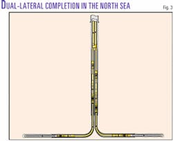
The Harding field, discovered in 1987, is in about 110 m of water. The targeted zone in the PS2yx was the Balder formation, an extremely permeable but unconsolidated sand that presented a considerable challenge for maximizing production from the two horizontal laterals while maintaining downhole sand control.
Like the Deepset Splitter, the FORMation Junction has two casing legs. The difference between the two is that one runs the FORMation Junction with one of the legs in a noncircular, half-moon shape. This results in a junction with a much smaller effective diameter that allows the junction to be run through smaller casing sizes.
BP selected this junction because it would save costs and rig time when placed in a smaller hole size at depths deeper than 9,000 ft MD. In this well, the junction had two 7-in. legs and was run through 133/8-in. casing and into a 12 1/4-in. open hole.
As mentioned previously, the project required sand control. For this, the job ran expandable screens sized for a 6-in. open hole that provided sand control while also minimizing hole size requirements and maximizing flow area.. This project marked the first use of expandable screens in conjunction with Level 6 multilateral technology.
As with the other Level 6 multilateral systems, this job placed the junction in the main casing string. A swaging assembly reformed the noncircular leg, landed horizontally at 9,346 ft MD in a single trip. The assembly, run on drill pipe, uses pressure applied to the pipe ID to create a piston force that quickly and easily drives the swage through the noncircular junction leg.
After the swage reformed the leg back to its original circular shape, the rig retrieved it from the well prior to pressure testing and cementing the junction and casing in place. A preinstalled diverter within the junction allowed the first leg to be cemented with conventional techniques immediately after the junction was in place and reformed.
The cementing job included a cementing string run into the first leg and standard float equipment. Calculated top of cement was at 8,000 ft MD.
With the junction now cemented in place, drilling operations began in the first leg. A 6-in. bit with MWD tools drilled the first 1,029-ft lateral to an 11,211 ft MD before the rig ran and expanded the screens in the target zone.
After the first leg was completed, the rig retrieved the preinstalled diverter and ran a second diverter to provide access into the other casing leg. The rig drilled the second 1,803-ft lateral to 11,178 ft MD. This second leg also included an expandable screen sized for the 6 in. open hole.
The well was ready for final completion after the rig retrieved the diverter.
Because both legs were in the same formation, BP could commingle the zones. With the well being offshore, however, BP required the ability to quickly, easily, and economically reenter either wellbore. To meet these needs, the completion included a lateral entry nipple (LEN).
In a Level 6 multilateral well, the LEN is part of the tubing string and lands in the junction assembly. The LEN provides flow control of either wellbore and allows selective reentry into either wellbore through the tubing.
In addition to the cost savings associated with slot recovery, the multilateral in combination with the expandable screens allowed for increased production from the well. At last report, the well was producing 30% more than similar conventional horizontal wells in the area.
Level 6 technology's future
Level 6 multilateral junctions provide low-risk, high-functionality systems that should continue to gain popularity. Basic concepts behind the technology are now proven.
The next step in the evolutionary process will add complementary technologies such as expandable screens and tubulars to provide maximum hole size below the multilateral junctions, thereby making multilaterals even more advantageous and cost-effective.
Advancements in intelligent well completions also will benefit multilateral applications by enhancing the ability to easily control production from multiple zones and wellbores.
Adding intelligent completion components to the straddle equipment in past Level 5 completions was a problem. With the fullbore access provided by Level 6 junctions, however, placement of intelligent components is not a concern.
It is only a matter of time before these technologies converge to provide an extremely efficient, optimized well completion.
The author

Cliff Hogg is a senior applications engineer in the emerging technologies-multilaterals group for Baker Oil Tools, Houston. He previously worked with Baker as a field engineer in West Texas and Oklahoma and as a production engineer for an independent operator in West Texas. Hogg holds a BS in petroleum engineering from Texas A&M University.