Brazos Midstream to double gas processing capacity of Midland basin Cassidy complex
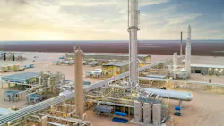
Brazos Midstream is adding a second 300-MMcfd cryogenic natural gas plant that will double processing capacity of subsidiary Brazos Midstream Operating III LLC’s soon-to-be commissioned Cassidy complex in Glasscock County, Tex., about 12 miles west of Garden City, in the Midland basin of the Texas Permian.
Scheduled to enter service in summer 2027, the newly proposed Cassidy II plant will join the operator’s previously announced 300-MMcfd Cassidy I plant—due for mechanical completion by November 2026 and startup by yearend—to lift the Glasscock County complex’s processing capabilities to 600 MMcfd and the operator’s overall nameplate capacity in Midland basin to 1.1 bcfd, Brazos Midstream said in a release Aug. 11.
Already supported by long-term acreage dedications covering about 575,000 acres now in full-scale development from and by the operator’s private and publicly traded producer customers, the proposed Cassidy expansion will enhance Brazos Midstream’s ability to further accommodate increased production in the region, the company said.
Presently equipped to accommodate 500 MMcfd of gas volumes in Midland basin following startup of its 200-MMcfd Sundance I and 300-MMcfd Sundance II gas plants in mid-2024 and early 2026, respectively, at the company’s Sundance complex in Martin County, Tex., anticipated startup of the Cassidy I plant later this year will enable the operator’s Midland basin processing system to handle already oversubscribed volumes.
Brazos Midstream said volumes currently moving from customers to the Sundance complex—equipped with an overall nameplate capacity of only 500 MMcfd—are exceeding 700 MMcfd following the recent addition of its new long-term contract with an unidentified supermajor.
“Our producer customers are accelerating development in deeper formations like the Barnett, with higher gas-to-oil ratios, dramatically increasing natural gas production across the Brazos system,” said Stephen Luskey, Brazos Midstream’s chief commercial officer.
“This growth coupled with our continued commercial success unlocks the next phase of our buildout [and our] ability to deliver this incremental capacity on an abbreviated timeline is a great example of our commitment to build critical midstream infrastructure ahead of planned development and to expand alongside our customers,” Luskey added.
Cassidy complex overview
According to official documents filed with Texas regulators in mid-July 2026 that revise earlier documents filed in late-September 2025 for the original Cassidy complex by now specifying installation of additional compressors and associated equipment at the site, the expanded version of the Cassidy gas processing project will tentatively include the following equipment and activities:
- Six 5,000-hp Caterpillar G3616 compressor engines.
- Ten 1,000-bbl vertical fixed-roof tanks for storing oily condensate.
- Two 1,000-bbl vertical fixed-roof tanks for slop storage.
- One 25.8 MMbtu-hr regenerator gas heater.
- One 59.4 MMbtu-hr heat medium heater.
- Two 89.5 MMbtu-hr stabilizer-amine hot oil heaters.
- One 2 MMbtu-hr TEG reboiler heater.
- Installations for truck-loading of condensate and slop oil.
- One plant flare.
- One thermal oxidizer.
- One tank combustor.
- Fugitive piping components.
- Various maintenance, startup, and shutdown activities.
Proposed plant processes
Pending approval and installation of all equipment included in the operator’s latest official project description, the two-train Cassidy processing complex’s compression station will receive natural gas at plant pressure via pipeline from various compressor stations, with inlet gas to first pass through an inlet separator that will provide two-phase separation of the gas.
The gas liquid will then be routed to the stabilizing and amine units, which will include two 89.5 MMbtu-hr hot medium heaters, one of which will be a true spare heater only be operated if the main heater becomes inoperable, according to official project documents.
Slop oil removed from the gas will be sent to two 1,000-bbl slop tanks, while condensate produced by the stabilizer will be routed to 1,000-bbl condensate storage tanks. Flash emissions, working and breathing losses, and losses from the loading of condensate and the slop and condensate tanks will be controlled with 98% destruction and removal efficiency (DRE) using a tank combustor.
Slop and condensate will be hauled offsite via tanker trucks, the documents said.
Gas will enter the dehydrator at the contactor tower where lean triethylene glycol (TEG) will contact the gas to remove moisture. Rich TEG from the contactor tower will be routed to a flash tank to allow entrained gas to flash off, with flash gas from the flash tank to be recycled for use as reboiler fuel.
Rich TEG from the flash tank will be sent to the TEG regenerator where it will be heated by a 2-MMbtu-hr natural gas-fired reboiler to boil off the captured water as steam. The regenerated, lean TEG will then be rerouted back to the contactor tower for reuse.
Steam discharge from the TEG will be routed to a benzene, toluene, ethylbenzene, and xylene (BTEX) condenser for recovery of liquids. Dried gas from the TEG dehydration unit will then directed to the cryogenic unit that will include a mol sieve dehydration unit with one 25.8-MMbtu-hr mol sieve gas heater and one 59.4-MMbtu-hr hot medium heater.
After separation, treated gas will then be sent through six compressors driven by six 5,000-hp Caterpillar G3616, natural gas-fired compression engines, with all engines to be equipped with an oxidation catalyst to control emissions.
Compressor blowdowns will be controlled with a 98% DRE by the plant flare, while amine and TEG flash-gas streams to be controlled by the thermal oxidizer.
To help control fugitive emissions—which occur via equipment leaks from valves, flanges, connectors, and other piping components—a variety of periodic planned maintenance, startup, and shutdown (MSS) activities will occur at the site, including blowdowns, tank degassing, pigging, rod packing, flare downtime, and fugitive-component repair-replacement works.
About the Author
 Robert Brelsford
Robert Brelsford
Downstream Editor
Robert Brelsford joined Oil & Gas Journal in October 2013 as downstream technology editor after 8 years as a crude oil price and news reporter on spot crude transactions at the US Gulf Coast, West Coast, Canadian, and Latin American markets. He holds a BA (2000) in English from Rice University and an MS (2003) in education and social policy from Northwestern University.