LNG CARGO HANDLING–Conclusion:Tandem pressures between ships during STS transfer cuts gas losses
Maksym Kulitsa
FSRU consultant
Odessa, Ukraine
David A. Wood
DWA Energy Ltd.
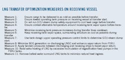
Lincoln, UK
Applying tandem pressures between discharging and receiving ships in an LNG transfer boosts vapor return, cutting cargo losses and reducing cost. Part 1 of this article described tank pressure and vapor and LNG temperatures' influence on ship-to-ship (STS) transfers (OGJ, Nov. 6, 2017, pp 74-81). Part 2, presented here, will focus on applying more advanced mitigative measures such as exploiting pressure differences between tanks to minimize cargo loss during STS transfers.
BOG, vapor return
The cargo-discharging LNG carrier (LNGC) can assist the receiving ship in efficiently handling its tank pressures and minimizing natural gas consumption in the gas combustion unit (GCU) or steam dump (SD). Not all natural gas vapor in the receiving ship's tanks can be relocated to the discharging ship while replacing the liquid LNG volume it discharges, but there are steps that can be taken to maximize this displacement.
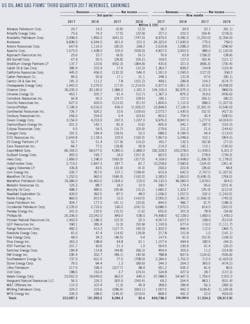
LNGC operators often unintentionally create conditions that reduce vapor return flow. By encouraging declining pressure in its tanks during an STS transfer, the discharging ship will generate vapor in its tanks beyond design specifications for normal boil-off rate (NBOR). The fact that tank pressure cannot stabilize much below the LNG's saturated vapor pressure (SVP) places a floor on pressure reduction and causes excessive vapor generation within the tanks of the discharging LNGC when intentional reduction is attempted. These vapors replace a large part of the reduced LNG volume, lowering vapor return flow from the receiving vessel. In some cases vapor returns have been reduced to 2-4 tons/hr instead of 9 tons/hr (see accompanying table).
The optimal safe and efficient balance is to maintain tank pressures in the discharging ship at or just above (+10-30 mbar) the pressure registered during the initial cargo survey when the custody transfer measuring system (CTMS) opened. This reference point will cause no complications for the discharging LNGC. The discharging vessel already has this tank pressure and the receiving floating storage and regasification unit (FSRU) legally cannot dictate the pressure that the discharging LNGC should maintain, its authority being limited to recommending that the discharging LNGC maintain CTMS-registered pressure during STS transfer. This will limit vapor generation on the discharging vessel to not more than NBOR and assure the best-possible tank pressure conditions to allow maximum vapor return flow from the receiving ship, the discharging LNGC's tank pressure matching its LNG's SVP.
To maintain CTMS-registered tank pressure, the discharging LNGC must use its vapor return valve. The correct application involving a 250-mbarg maximum allowable relief valve setting (MARVS) FSRU requires the vapor return valve to be at least mostly open and tank pressure to be very close to (ideally equal to), but generally not above, the CTMS-registered value.
Low differential-pressure availability in certain rare cases will cause the LNGC to have a cargo with high but still safe SVP and associated tank pressure. LNGC tank pressure during the initial cargo survey may be so high that, even with the FSRU tanks at their upper operating-pressure limit, the differential pressure will be too low to allow high BOG return flow. In this case, LNGC tank pressure must be slowly lowered in steps and vapor return flow observed. Vapor return flow increases as LNGC tank pressure lowers progressively. But at a certain LNGC tank pressure during the pressure-lowering process vapor return flow will start to decrease again. That tank pressure on the LNGC represents a balance point where vapor return can be maximized for prevailing conditions.
Locating this pressure balance point can be attempted slightly before the FSRU tanks reach their upper operating-pressure limit if it is apparent that BOG return flow is too low for the typical values expected for specific STS transfer. The key focus of this balancing effort is to maintain CTMS pressure if MARVS of the FSRU and LNGC are the same or maintain CTMS +10-30 mbar in the discharging LNGC's tanks if an FSRU with MARVS >250 mbarg is involved. These levels must be achieved by adjusting the vapor return valve. It would be fully open in case of 250-mbarg MARVS and throttled in cases where STS transfer involves FSRU with 400-700 mbarg MARVS tanks.
LNGC typically arrive at the FSRU site with tank pressures of 110-130 mbarg, a safe and acceptable pressure for the duration of the STS transfer. If the discharging LNGC decides to lower tank pressure to 70-80 mbarg and attempts to maintain its tank pressures at that level then a portion of the LNG volume discharged from its tanks will be replaced by vapor resulting from the evaporation above NBOR in its tanks when pressure dropped below the LNG's SVP. Under such circumstances the vapor return valve will be throttled and the receiving vessel will be forced to retain more vapor in its tanks. That retained vapor may eventually need to be disposed of by running the GCU-SD.
The vapor return rate will vary during STS transfer. As the receiving ship's tank pressure rises vapor return flow is boosted toward the discharging LNGC. If the discharging LNGC attempts to maintain its tank pressure significantly below CTMS-registered value, LNG liquid in its tanks cools. That cooling effect may be observed only during last third of STS transfer at the receiving vessel.
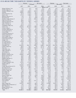
The cooling of the cargo in this manner is insignificant (< 0.5° C.) and its beneficial impacts for the receiving ship negligible. Only the last quarter to one-third of a cargo transfer might enter FSRU tanks at this slightly lowered temperature. Gains provided by discharging LNGC while able to receive significant return vapor by maintaining tank pressures closer to CTMS-pressure far outweigh this cooling effect's benefits (Fig. 1).
In general, applying this measure in case of STS transfer between LNGCs would suggest broadly the same tank pressure reference point for the discharging LNGC (as recommended for STS transfers involving 250-mbarg MARVS FSRU) even when both LNGCs must use GCU-SD to keep their cargoes as cold as possible and deal with increasing tank pressures.
Doing so, however, depends on the prevailing conditions in the two ships. When the discharging LNGC also runs its GCU-SD (the typical situation in this type of STS transfer) and promotes conditions that result in the vapor return valve being only partially open, the LNGC generates additional vapor in its own tanks, above NBOR, which it burns immediately in its own GCU-SD. Its cargo is not significantly cooled before transfer to the receiving LNGC, with only minor practical benefit to the receiving ship.
Alternatively, the receiving LNGC may be inhibited from using its upper operating pressure limit, and instead target maximum cooling of the received cargo. The resulting lower pressure differential between the ships' tanks inherently leads to reduced vapor return flow to the discharging LNGC.
The best solution in this instance is for the discharging LNGC to fully open the vapor return valve and maintain tank pressure close to the CTMS reference point by running its GCU-SD. Doing so creates the ideal pressure differential between the ships, indirectly connecting the discharging ships GCU-SD to cooling the cargo on the receiving LNGC while also running its own GCU-SD. Higher LNG transfer rates are an additional benefit of applying this measure to STS transfer.
When the receiving LNGC can maintain upper operating pressure limits in its tanks (e.g. the received cargo will be discharged to a 700-mbarg MARVS FSRU, not 250, or a shore-based terminal which has confirmed its agreement to receive a warmer cargo), application of this measure would be the same as for transfer to an FSRU. It is, however, still prudent for the discharging LNGC to maintain its tank pressure reference close to and not above CTMS-registered pressure, best achieved by opening the vapor return valve as fully as possible.
Applying tandem pressures
Tandem pressures are created when the receiving ship can push maximum vapor return flow and the discharging ship can accept maximum vapor return flow. This involves applying Measures 7 and 8 (see accompanying box) in tandem. This tandem-pressures approach is critical for STS transfers involving FSRU with 250-400 mbarg MARVS tank design, but less important for 700 mbarg vessels. Applying the tandem-pressures approach in LNGC-to-LNGC transfers is only possible if warmer cargoes are acceptable by the next port of discharge. Low differential pressure between tanks prevents tandem pressures from developing maximum flow, the upper operating pressure limit (Measure 7) not applying if a cold cargo is required.
Allowing tank pressures to naturally rise to the upper operating tank pressure reference point for the receiving ship initiates the tandem-pressures approach, higher tank pressures on the receiving ship pushing more vapor return to the discharging LNGC tanks during STS transfers. Tandem pressure also results in minimum generation of boil-off on the discharging ship (Measure 8) and maximum differential pressure between the ships, stimulating significant vapor return flow. Returning more vapor to the discharging ship enhances Measure 7's benefits. Measure 9 provides a double benefit: those achieved by Measures 7 and 8 and the ability to push vapor return to the discharging ship (Fig. 2). Measure 9 therefore secures the largest achievable vapor return flow between ships during STS transfer in prevailing conditions.
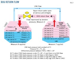
Optimization Measures 8 and 9 must be carefully discussed during the pretransfer meeting, operators of discharging LNGC likely being unaware of the mutual benefits of such practices. Communication between discharging and receiving ships' cargo operators is essential during all stages of an STS transfer to apply Measures 8 and 9 effectively. For instance, timely communication during tandem-pressure operations from the discharging vessel before each adjustment of its vapor return valve ensures safe operations. Carefully coordinated adjustments to the discharging ship's vapor return valve also are required, especially when the receiving ship's tanks are close to their upper operating pressure limit. As these measures involve nonroutine operations, they require a formal risk assessment relating specifically to them.
Operator induced heat reduction
This measure minimizes induced heat ingress within FSRU tanks and thereby minimizes LNG cargo heating within those tanks. LNG must maintain a pressure subcooled state when FSRU tank pressure reaches its upper operating limit. Such circumstances require a difference between the LNG's SVP and the prevailing tank pressure (tank pressure being greater) to reduce vapor emissions from the LNG's surface to a minimum, much lower than NBOR. The benefit in these circumstances comes from running GCU-SD at lower rates, rates that maintain the tank pressures close to the upper operating pressure limit and without the objective of cooling the LNG when SVP approaches the upper limit. This reduces GCU-SD consumption to a minimum.
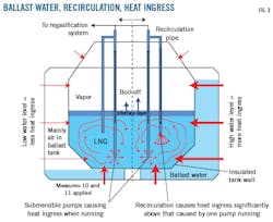
A significant amount of tank heat ingress is caused by the intank regasification feed pumps, particularly when these are allowed to run in excessive recirculation mode (Fig. 3). Many operators like to have spare regasification plant feed pumps in case one trips or fails, allowing all available pumps to run at excessive recirculation. Modern FSRU generally are equipped with robust regasification feed pumps in their tanks. These operate reliably once LNG liquid levels are 1-3 m above the base of the tank with a very low chance of tripping.
It is not prudent to run extra regasification feed pumps when LNG levels allow the required number of pumps to run stably. Additional regasification feed pumps, regardless of excessive recirculation effects, should only be started when currently running pumps show signs of unstable operation or there is not enough LNG feed pressure for the regasification plant, which is rare.
Starting a standby regasification feed pump in the event another intank regasification feed pump trips takes little time and is unlikely to cause the whole regasification plant to trip. It is therefore easy to avoid excessive recirculation of LNG through the regasification plant feed pumps, preventing excessive heating of the LNG cargo both before and during STS transfers. This measure is of the utmost importance on 250-mbarg MARVS FSRU and is also very important for 700-mbarg vessels.
Removing ballast water
For 250-400 mbarg MARVS membrane tank FSRU it can be beneficial to discharge ballast water surrounding the LNG tanks as soon as vessel stability, strength limitations, and draft considerations allow. Doing so reduces heat ingress into LNG tanks, water being a better conductor of heat than air. It is only effective to remove ballast water until the water level in the ballast tanks ceases to wet the outer walls of the cargo tank (Fig. 3).
This measure only slightly reduces natural heat ingress into FSRU tanks and thereby only slightly reduces LNG cargo heating as well. It is typically only worth implementing for 250-400 MARVS vessels, which have a smaller margin available between SVP and upper operating pressure limit. This measure also can indirectly lead to less GCU-SD gas consumption for tank pressure control at upper pressure limits.
Regarding LNGC-to-LNGC transfers, both vessels can benefit a little by reducing the natural heating of the cargo, leading to a small reduction in boil off gas. The receiving LNGC should act as the FSRU with respect to ballast. The discharging LNGC should maintain ballast just below the point at which the cargo tanks become wetted by the ballast water for as long as possible, and then take ballast onboard as slowly as possible to maintain stability, trim, and draft within safe limits. Estimated ballast-water-induced extra boil off is approximately 500 kg/hr for an entire ship, a potentially important difference for this sort of STS transfer.
Return vapor flow
This measure is applicable at the end of STS transfers in cases where vapor return to the discharging LNGC is sufficient and STS transfer is conducted at a tank pressure on the receiving ship below its upper operating pressure limit with the GCU-SD not yet running (Fig. 3). The slowdown of LNG flow as STS transfer nears completion usually is specified in the pretransfer meeting to last 40-60 min. The discharging LNGC should be instructed to avoid sudden changes in liquid flow rate and to operate the vapor return valve very smoothly and communicate any changes to the FSRU so that it can reduce vapor return flow if needed.
The receiving ship's tanks are likely to reach their upper operating pressure limit during this stage of the transfer. GCU-SD or similar equipment must be started and run at a rate sufficient to maintain tank pressure at this point but not necessarily reduce it (Fig. 1). Tank pressure will decline naturally during STS ramp down by at least 30-40 mbar as the transfer rate slows. The GCU and other safety equipment also may slow to minimum flow, remaining on standby for unexpected events, or shut down completely at the end of the STS transfer. It is unwise to run GCU-SD for cargo-cooling purposes on any FSRU after an STS transfer is complete. Doing so if FSRU tank pressure is within its permitted operating range loses cargo without producing any benefits.
In the case of an LNGC-to-LNGC STS transfer, the receiving LNGC must be prepared to allow its tank pressures to rise to near their upper operating pressure limit during this stage of the STS transfer, including flow rampdown. It is generally not necessary for the receiving LNGC to prevent tank pressure increases, even when it has cool-cargo obligations and its GCU-steam dump is already activated. Tank pressure would typically only remain elevated for up to about 1 hr, insufficient for the entire cargo of LNG to warm perceptibly. Indeed, cargo heating would be so small it would be unlikely to register more than +0.1° C. (+10 mbar). Adopting this approach is likely to save only 5-10 tons of BOG from being burned in the GCU during each STS transfer, equivalent to a cargo value of about $1,900.
Benefits
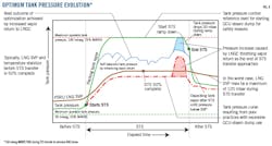
During normal operations, adopting the proposed cargo management measures on FSRU with MARVS more than 250 mbarg (e.g., 400 or 700 mbarg) and a recondenser or latent heat capture system (LHCS) running should reduce consumption of gas by the GCU-SD to zero. Any gas consumption in the GCU of such vessels is likely to be due to inefficient operations.
On 250-mbarg MARVS FSRU, adopting the proposed cargo management measures, with or without a recondenser or LHCS installed, should cut gas consumption in GCU-SD operations by one-third to one-half (Fig. 4). Exact benefits, however, depend on many factors and vary from one STS to another. For instance, if the discharging LNGC arrived with a cold or very cold cargo or the gas send-out rate from the FSRU was high, more flexibility would be possible in tank pressure management, resulting in lower gas consumption by GCU-SD.
For LNGC-to-LNGC STS transfers, loss reductions by adopting the proposed cargo management measures are less than for LNGC-to-FSRU and are likely to vary significantly from one STS transfer to another. But savings valued in the thousands or tens of thousands of US dollars per STS transfer can still be achieved.
The tandem-pressure approach (Measure 9) achieves the most significant savings. This measure can be applied with FSRU of any specification. Applying the upper operating pressure limit on FSRU tanks for starting safety equipment such as the GCU-SD (Measure 7) also leads to substantial reduction in gas consumption and avoids cargo loss (Fig. 1).
The most disadvantageous FSRU cargo operator's action is unjustified excessive recirculation of the regasification plant in-tank feed pumps (Fig. 3).
Bibliography
International Group of Liquefied Natural Gas Importers (GIIGNL), "Rollover in LNG Storage Tanks," 2nd Ed.: 2012-2015, public version.
Hashemi, H.T. and Wesson, H.R., "Cut LNG Storage Costs," Hydrocarbon Processing, August 1971, pp. 117-120.
Kulitsa, M. and Wood, D.A., "Rigorous monitoring reduces FSRU cargo-rollover risks," Oil and Gas Journal, Vol. 115, No. 6, June 5, 2017, pp. 74-81.
Zellouf, Y. and Portannier, B., "First step in optimizing LNG storage for offshore terminals," International Gas Union Research Conference, Seoul, Oct. 19-21, 2011.