High-temperature fracturing converts geothermal exploration well
Newberry Volcano in central Oregon contains ideal conditions for a superhot rock enhanced geothermal system (EGS) candidate. An exploration well needed to be converted to an injector well to produce heat through a fracture network between this injector and a producer well. Converting the exploration well to an injector required propped stimulation at greater than 300 °C. (572 °F.) downhole temperatures, running the world's first high temperature sleeve, and successfully pumping through it for the stimulation.
Volcanic EGS
Newberry Volcano in central Oregon contains ideal conditions to be a superhot rock enhanced geothermal system (EGS) candidate. Long-term geological and geophysical investigations have established the presence of a substantial conductive thermal anomaly with temperatures exceeding 320° C. (608° F.) at 3,000 m TVD and projections of more than 400° C. (752° F.) below 4,000 m. The relatively shallow depths and high enthalpy provide advantageous conditions for drilling and production.
The volcano’s intersection of the cascade volcanic arc, Columbia Plateau, and Basin and Range province, produced a complex magmatic history with more than 600,000 years of activity. It erupts a mix of basaltic, andesitic, and rhyolitic material. The nested caldera within the 50 × 30-km elliptical edifice contains numerous post-caldera features such as obsidian flows and maars. Both caldera-related and regional faults cut through the flanks and interior of the volcano, producing complex structures and potential fluid pathways.
Newberry Volcano subsurface structural and geomechanical characterization include lithologic data from well logs and cuttings, seismic velocity tomography, magnetotelluric (MT) surveys, gravity surveys, and InSAR coverage. These data reveal variable rock properties relevant to EGS development.
For example, brittle lava flows, welded tuffs, and intrusives respond well to hydraulic stimulation, while volcaniclastic and clay-rich units tend to deform plastically, producing inferior propped structures. A geologic model identified ideal reservoir zones containing superhot rocks with suitable mechanical properties for EGS development.
EGS wells
Deep exploration well NWG 55-29, drilled on the northwestern flank of the volcano in 2008, revealed a 350° C. (662° F.) bottom-hole temperature. Additional exploration wells encountered temperatures greater than 315° C. (599° F.) below 2,740 m, though these locations had insufficient permeability for conventional hydrothermal service.
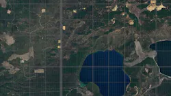
NWG 55-29, drilled in the west flank away from surface expressions of mapped caldera ring fractures, was on the edge of a high-gravity anomaly which revealed several high-density intrusions (Fig. 1). The well’s open-hole interval spanned 1,903-3,066 m MD and intersected microcrystalline granodiorite at 2,627 m MD. The well intersected another 11 granodiorite (29 m average thickness) or felsic (9 m average thickness) dikes or sills with alternating subvolcanic basalts.
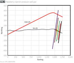
This exploration was reentered and stimulated to become an injector well. Twin producer well NWG55A-29 has been drilled and recently stimulated to connect the wells and harvest heat through a fracture network between injector and producer (Fig. 2). The EGS design included iterations of hydraulic vs. propped half-lengths with respect to their effect on heat harvesting potential. Propped half-lengths were the main drivers for engineered reservoir volume.
Challenges to the completions included propped stimulation at greater than 300 °C. (572 °F.) and running the world's first high-temperature sleeve and successfully pumping through it.
High-temperature stimulation
The migration of NWG55-29 from exploration to injector required novel stimulation and well intervention contingencies. The most prominent problem was a casing-in-casing reentry requiring perforating through two strings and a formation composed of basalt, basaltic andesite, granite, and granodiorite.
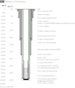
The existing completion had a 7-in. perforated liner and was covered with a 4.5-in., 11.6 lb/ft P-110 liner after recompletion for geothermal operations (Fig. 3). Perforations were required through the new 4.5-in. casing and original 7-in. pre-perforated liner.
Pretreatment used abrasive perforating and dynamic diversion with coiled tubing to cut through the casings and access the formation. A hybrid conventional- and coiled-tubing stimulation equipment spread provided either dual injection pressure pumping with abrasive perforating and dynamic diversion or conventional plug-and-perforate intervention with bullhead stimulation. Both processes included multistage fracturing options.
The completion subsequently used a combination of abrasive jetting and conventional shaped charge perforating. The lower two intervals used standalone abrasive jetting, but the upper four intervals used a combination of plug and perforate and abrasive jetting. Based on diagnostic pumping response, some were single-process intervals, while others combined perforating processes.
A simple dual injection approach provided fast on-location stimulation and intervention changes to separate clean fluid from proppant-laden fluid. A simple valve change from the treating line to either the coiled tubing unit or the wellhead, combined with isolation of two high-pressure pumps, produced near-instantaneous changes while pumping up to 40 bbl/min. This approach applied to both coiled tubing dual injection and conventional bullhead treatments.
A yard test evaluated jetting perforation in the casing-in-casing condition, which had significant standoff between the jetting tool and 8.5-in. open hole. The tests used a single 0.1875-in. jet within a full tungsten carbide jetting sub aligned perpendicular to the face of a granite boulder with 4.0-in. standoff between the jet OD and granite face. A 30 cp guar-based linear gel was pumped at rates of 1.1 bpm or 1.3 bpm with 80-mesh mineral garnet introduced once rate and pressure stabilized.
Abrasive jetting testing continued under steady-state conditions for 30 min. The 1.1-bbl/min jet cut a 7.8-in. deep hole, and the 1.3-bbl/min jet cut a 9.9-in. deep hole. Hole sizes were 1.5 in. × 0.85 in.
Well 55-29 was stimulated using high-viscosity friction reducer (HVFR) (OGJ, Apr. 9, 2024) to maximize proppant transport, limit formation damage, and provide environmentally compatible chemistry for the sensitive Central Oregon volcanic wellsite. Pressurized rheometer testing to the 243 °C. (470 °F.) upper temperature limit showed that the fluid thinned at 107 °C. (225 °F.) and had almost no viscoelastic transport properties even at a high 10-gal/Mgal concentration of HVFR.
Based on these results, cooldown modeling produced a range of temperatures which would be encountered during the stimulation process, showing that, under these conditions, dynamic fluid properties under variable shear rates optimized pre-treatment propped-fracture modeling and pump schedule.
Pretreatment
Abrasive jetting and fluid testing guided the perforation and propped-fracture stimulation. For jetting, a 7.8-bbl/min minimum rate pumped through a 6 × 0.1875-in. jetting sub averaged 1.3 bbl/min per jet at 3,500-psi minimum pressure drop. This broke down the formation and provided directed dynamic diversion for commingling tubing and annular flows into the developed hydraulic fractures.
In-treatment zonal isolation testing validated the effectiveness of the dual-injection dynamic diversion process. Sand plugs placed between intervals isolated zones. The dynamic diversion process worked if the same treating-pressure was observed after the end of the previous treatment but before the initial breakdown of the subsequent treatment. In this case, no interference existed between zones, and no discrete mechanical intervention was required for isolation.
Significant natural fissures and fractures were expected in the NWG 55-29 target formation, possibly leading to low fluid-efficiency due to hard rock pressure-dependent leakoff (PDL) or transverse (TS) hydraulic-fracture growth and fluid storage. A pretreatment diagnostic pumping program identified the PDL coefficient or TS ratio.
In the event of high losses, dry bulk amorphous silicate microparticle material with about 300 mesh non-API mean size distribution served as a fluid loss agent. For formation sections with a low PDL, front-end microparticle treatment sufficiently controlled total fluid loss. Under high PDL, mid and late portions of the stimulation treatment received additional fluid-loss treatment. Controlling fluid loss through these methods yielded consistent surface and bottom-hole treating pressures.
A permanently installed temperature and acoustic sensing fiber optic determined whether wireline-deployed intervention tools could survive the residence time of intervention after jetting, given the high warm-back expected in this environment.
With the dual-injection plan qualified, multiple coiled tubing runs targeted stimulation treatments up to a total downhole rate of 20 bbl/min. The fiber installed during the recompletion phase functioned as designed and did not suffer malfunctions during the NWG 55-29 stimulation. Multiple cooldowns and warm-back cycles were monitored to understand temperature changes during stimulation and implications of such changes on the ability to achieve desired stimulation goals.
Multi-fracturing treatment
Upper zones were completed with a typical perf-and-plug scheme, but perforation charges and frac plugs had to be tailored to the high-temperature environment. A combination of tubing-deployed sand plugs, high-temperature flow through composite frac plugs, and a combination of the two when operationally required were executed based on the diagnostic pumping and operational response conditions.
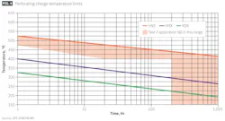
Fig. 4 shows time-temperature limitations of common perforating explosives available for geothermal well completions. Due to the tight mobilization timeline and limited availability of high-temperature compatible HNS charges, a HMX explosive charge was chosen for its charge efficiency and temperature compatibility with the expected downhole residence time and temperature.
The targeted rock contained granite with about 2-4% porosity and 25,000-psi unconfined compressive strength (UCS). A 1.14-psi/ft overburden gradient at about 9,750-ft TVD resulted in 28,500-psi confining stress. These combined factors significantly limited perforation tunnel penetration length into the formation.
The smaller diameter liner of the recompletion also limited the diameter of the perforating carrier which resulted in a 3 ⅛-in. carrier loaded with a 22.7-gram shaped charge with 6 shots/ft (spf) and 60° phasing.

A 3.5-in. high-pressure high-temperature (HPHT) composite frac plug isolated stages and was chosen based on its successful track record in applications up to 204.4° C. (400° F., Fig. 5). The plug contains a filament wound S-type glass and high-temperature resin body with a rubber element isolation system with thermoplastic backup rings for element mechanical support.
Cast iron slips anchor the plug into the casing wall, locking in the setting force and holding the force generated under applied differential pressure. A 1.75-in. ball isolated the plug ID.
The plug was tested in a chamber heated to 177° C. (350° F.) for 1.75 hr, the maximum available for the test. Cyclic pressure was applied above the plug to simulate max allowable pressure and pressure cycles that occur during well operations. Based on these tests, the plug was rated to 15,000-psi differential from the top at 177° C.
The frac plug was deployed without the ball in place via wireline using a common setting tool. Due to the test-temperature constraint, and to reduce failure risks in the field, the well was cooled to below 177 °C. before setting by injecting cold fluid from the surface and monitoring the temperature with the installed fiber optics.
After setting the plug, the ball was launched from the surface to seat on the top of the plug and isolate the ID, ensuring pressure isolation from the stage below. This type of plug and ball-drop methodology was applied to ensure a flow path for fluid pumping and to cool the plug if subsequent stage stimulation was delayed
After the plug was set, another wireline run created the perforations above the plug to access the formation. Following this step, the isolation ball was pumped from surface to land on the plug and isolate the stage below. After completing the stimulations, coiled tubing drilled out the plugs using a milling BHA.
Stimulation design, monitoring
At temperatures exceeding 300 °C. (575 °F.), conventional sand and resin-coated sand often fail due to crushing, dissolution, or chemical alteration. Conventional ceramic proppants maintain structural integrity, thermal resilience, and higher conductivity in SHR fractures. Ultra lightweight ceramic (ULWC SG 2.0) and lightweight ceramic (LWC SG 2.71) proppants provide better transport and long-term conductivity relative to high-density ceramics. Long-term, high-temperature conductivity tests showed that 40/70 mesh LWC and ULWC ceramic proppants met all requirements.
Nanoparticle tracers quantified the flow behavior of individual stages and outline variations in flow contribution across all stages were premixed in liquid form and pumped with the stage treatments.
Stage 1 utilized three unique tracers distributed throughout the stage (from pad to flush), while Stages 2 and 3 each featured two unique nanoparticle tracers. Stages 4 and 5 each included a single unique nanoparticle tracer.
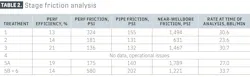
Acoustic friction analysis quantified pipe friction, perforation friction, perforation efficiency, and near-wellbore tortuosity using water hammer waveform analysis. Acoustic measurements were recorded during stimulation and at the end of the stage after pump shut down.
Water-hammer waves attenuate from pipe friction and change sign and shape from well ID changes and hydraulic connections through perforations and the near-wellbore region to fractures. This approach, unlike step rate tests, separates pipe friction from perforation and near-wellbore tortuosity friction.
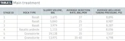
Stimulation, production
Basaltic layer stimulation required higher average treating pressures than the granodiorite or felsic layers but had higher amounts of placed proppant (Table 1).
Acoustic measurements were taken at various times during all stages except Stage 4 which experienced operational problems. Perforation efficiency was consistently low at about 15% (Table 2). Pressure losses from near-wellbore tortuosity were above 1,000 psi at a roughly 30-bbl/min rate in all but one stage. Pipe and perforation friction were 130-580 psi due to the relatively low treatment rates.
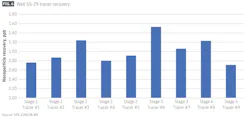
Tracer recovery revealed significant variations in flow across the stimulated stages (Fig. 6). All tracers were detected in the initial sample showing good communication between each fracture interval and the wellbore, with a caveat that vertical communication may happen between fractures causing tracer recovery regardless of flow distribution from the fracture intervals.
Seismicity during stimulation
The Lawrence Berkeley National Laboratory (LBNL) seismic-monitoring network tracked NWG 55-29 stimulation within 5 km of the well and 300 m deep. Additionally, hundreds of nodes installed in an array centered on NWG 55-29 monitored the stimulation of NWG 55A-29. This increase in sensors, coupled with fiber optic DAS measurements, improved the ability to detect seismic activity and reservoir characterization for activity at Newberry Volcano.
A traffic-light system monitored the stimulation operations. If an event occurred with magnitude exceeding thresholds defined in the Induced Seismicity Mitigation Protocol (ISMP), text and email alerts were sent to relevant parties. Upon review by a competent person, the event was displayed in near-real-time on a public website.
The stimulation induced remarkably little seismicity. A few low-magnitude events, which were too small to be reliably located using the permanent seismic array, were corroborated by the distributed acoustic sensing data collected from the well’s fiber optic array. This seismicity, combined with the latest data from the stimulation of the adjacent producer, confirms stress-orientation fracture propagation geometry expectations.
Based on “Enhanced Geothermal System Propped Stimulation >300°C: From Design to Implementation Phase I,” SPE-228078-MS, SPE Annual Technical Conference and Exhibition, Houston, Tex., Oct. 20-22, 2025.
About the Author

Alex Procyk
Upstream Editor
Alex Procyk is Upstream Editor at Oil & Gas Journal. He has also served as a principal technical professional at Halliburton and as a completion engineer at ConocoPhillips. He holds a BS in chemistry (1987) from Kent State University and a PhD in chemistry (1992) from Carnegie Mellon University. He is a member of the Society of Petroleum Engineers (SPE).