Here are factors that govern evaluation of mechanical damage to pipelines

Mechanical damage is a leading cause of significant failures in pipelines and the number one cause of pipeline incidents reportable to the US Department of Transportation. It accounts for at least one of every three pipe-related incidents in gas and liquid products pipelines.
The characteristics of mechanical damage have been a subject of study since the mid-1950s. While a simple damage-assessment criterion has so far eluded researchers' best efforts, the results of tests and service experience have revealed many factors important for the operator to consider when responding to damage on a pipeline.
Two forms of damage
Mechanical damage commonly manifests itself in one of two forms. The first and most serious is encroachment (third-party) damage that occurs when the pipe is struck by earthmoving equipment.

This usually consists of a shallow residual dent, plus a gouge. This sometimes is called a "combined defect" because it consists of both a geometry distortion and a stress-concentrator or notch.
The other important form of damage occurs mainly during construction of the pipeline. Most often the damage appears as prominent dents on the bottom half of the pipeline, often called "plain dents."
Encroachment damage
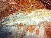
Fig. 1 shows examples of encroachment damage. Common causes include contact from excavators, graders, ditchers, plows, directional drillers, and just about any other sort of equipment used to penetrate or move soil.
General excavation is the most common source of damage, but everything from roadwork to farming has caused incidents, including the pipeline operator or his contractors hitting his own line.
Offshore, encroachment damage comes from contact by ship keels and anchors.
Two aspects of encroachment damage interact to cause particularly serious defects for pipelines:
- Metallurgical damage in the scrape or gouge.
- Rerounding of the dent under the influence of internal pressure.
Metallurgical damage occurs when the striking object contacts and slides along the pipeline surface. Visually, the damage appears as a scrape or gouge and might not look very severe.
But within the scrape or gouge, plastic flow, metal transfer, and even remelting due to the heat of friction would have occurred at the contact point. For some depth below that, the microstructure is crushed and severely cold-worked, locally degrading the ductility and toughness.
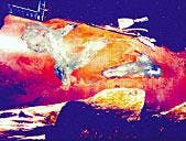
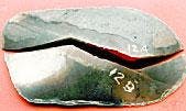
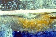
This type of damage is evident in a cross section at the root of a gouge. Fig. 2a shows a cross section of a fracture at a gouge. Fig. 2b shows the severely crushed microstructure in the gouge just below the pipe surface, as well as cracks which often form due to "rerounding."
As the contacting object indents and scrapes along the pipe surface, the pressure in the pipe immediately pushes the dent back out (in other words, the dent "rerounds") behind it.
As the dent pushes out, very high tensile strains develop in the root of the scraped or gouged area and may cause cracks to form in the cold-worked, reduced-ductility metal. If the pipe does not fail right away (which actually occurs in about 80% of encroachment damage failures), a crack is left that can grow in service. The crack may not be visible to the naked eye.
Although the residual dent depth is usually very shallow, tests have shown that the dent never fully rerounds, which means that it continues to fluctuate in and out with changes in operating pressure.
It can take many cycles of pressure for the dent to "shake down" to elastic action, which means that plastic strain can continue to accumulate in the damaged area. If the damage survives shakedown, the dent will subsequently cycle elastically over a smaller range of motion, providing a mechanism for continued crack growth by fatigue in service.
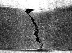
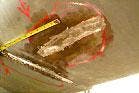
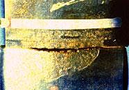
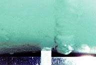
The interaction of metallurgical damage with rerounding behavior (described above) explains the delay of many mechanical damage failures. Encroachment-damage failures typically occur in the crease left by the striking equipment (Fig. 3).
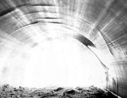
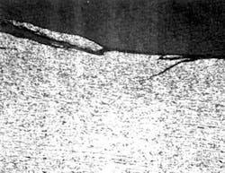
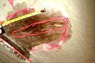
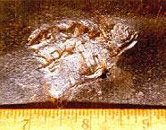
Multiple creases are often present where such damage occurred, such as that shown from the inside of a pipe in Fig. 4.
Encroachment evaluation, repair
There is no reliable method for evaluating the safe operating pressure or the safe time-to-failure of pipe affected by encroachment damage.
When such damage is found, the operator should be prepared to make a repair as soon as possible. Moreover, when entering a ditch to investigate possible encroachment damage, the operator should reduce the line pressure by at least 20% to provide safety for the workers because the damage could fail at any time.
Several repair options are available to the operator. Steel sleeves designed for pressure containment are always an appropriate repair method. And composite wrap repairs are acceptable, provided the following steps are taken:
- The scrape or gouge is ground down to a smooth contour.
- The damaged area is inspected to verify that any cracks have been removed by grinding.
- The residual indentation is filled with a hardenable filler under the sleeve.

Where the damage is light, it may be sufficient simply to grind out the damage and repair the coating. The safe length and depth of grinding may be determined from the equation (see box on this page).
The maximum safe depth of grinding is 40% of W.T. The pipe surface should be inspected to verify removal of any cracking and to check the remaining wall thickness.
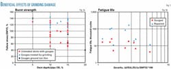
The effectiveness of this repair technique was demonstrated by the following methods:
- The burst strength of pipe containing combined defects severe enough to cause failure at low stress was increased to well above 100% of specified minimum yield strength (SMYS) by grinding them out (Fig. 5a).
- The pressure-cycle fatigue life of pipe containing combined defects was increased by a factor of 2-10 by grinding them out (Fig. 5b).
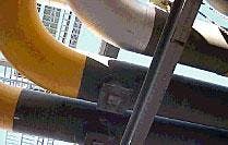
Fig. 6 shows a pair of 36-in. OD gas flare lines that were damaged when they fell off their pipe rack during a plant upset. The repair is being made by careful grinding to a smooth contour, accompanied by surface non-destructive examination (NDE).
Construction damage
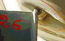
Fig. 9 (below) shows examples of damage resulting from poor pipe installation. In every case, the pipe was inadequately protected from settlement onto rocks in the ditch bottom.
In general, urethane or styrofoam pillows are inadequate supports under the combined weights of the pipe, overburden, and hydrotest water or product inside the pipe.

Rock shield wraps and thin-setting, epoxy-based concrete coatings are effective protection against corrosion in rocky soils but cannot prevent indentation of the pipe due to settlement. Heavy concrete coating (1 in. or thicker) provides more-effective protection from rock, although it can be penetrated by sharp rocks.
Graded fill materials (sand) can provide adequate padding when properly installed. Setting pipe on regularly spaced sandbags in the ditch and pouring the padding over the pipe will leave an unfilled gap below the pipe, resulting in spanning over the supports and settlement of the pipe into the gap.
The most effective way to prevent damage in the ditch is to diligently remove rocks from the ditch bottom or pour in a generous bed of padding sand or fines before laying in the pipe.
Other forms of construction damage besides indentation can occur, such as scrapes, dents, or buckles. The scrapes and dents are essentially similar to the encroachment damage suffered in service. They should be cut out if found before the pipeline enters service, or repaired the same as encroachment damage if found later.
Rocks in the ditch or backfill tend not to produce metallurgical damage of the extent observed in backhoe hits, although some localized metal damage is possible if the rock is hard and sharp.
Also, the rock-induced indentations are restrained from rerounding by the surrounding earth. Unlike encroachment damage, therefore, rock damage does not pose an immediate threat to pipeline integrity.
Rather, conditions are established for potential long-term problems such as:
- Coating damage.
- Shielding from cathodic protection.
- Corrosion.
- Stress-corrosion cracking (SCC) or hydrogen cracking.
- Punctures due to continued settlement
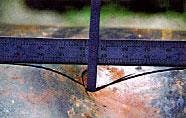
Fig. 8 shows examples of these problems. Failures caused by rock punctures occur as leaks; failures caused by corrosion or environmental cracking-that develops as a result of rock damage-may occur as ruptures.
Rocks have been documented in at least 5% of reportable incidents caused by corrosion, but the actual contribution of rocks to corrosion problems is likely higher.
A couple of other surprising problems associated with rock dents have been observed on operating pipelines. One is the occurrence of fatigue cracks or SCC in the saddle-shaped area between closely spaced dents. Tests show that the saddle area has a large radius of curvature and is unrestrained from flexure, creating a mechanism for cyclical crack growth.
A second problem has been the occurrence of fatigue cracks in a rock dent that was excavated, the rock removed, and the coating repaired. Removal of the rock left the dent unrestrained and free to fluctuate in response to changes in operating pressure, leading to fatigue.
This has only been observed in liquids pipelines, due to their more intensely cyclic operating spectrum compared to gas pipelines. In fact, tests have shown that the pressure-cycle fatigue life of dents restrained by rocks is at least an order of magnitude greater than that of unrestrained rocks.
This suggests that operators of liquids pipelines might be better off leaving rock dents in place and focusing on corrosion inspection and control.
Construction evaluation, repair
Rock-induced damage can be repaired by a number of methods, including:
- Welded steel sleeves, either designed for internal pressure, or with the ends left unwelded (a hardenable filler in the dent space being recommended in either case).
- Composite wrap repair with hardenable filler in the dent space.
- Repair to the coating only (appropriate for gas pipelines).
Present regulations and industry codes indicate that dents deeper than 6% of the pipe OD should be repaired. Historically, the main consideration behind the 6% criterion was to accommodate pigging.
While the 6% criterion probably leads to repair of many of the most damaging rock dents, the severity of the dent is not uniquely a function of depth alone.
Punctures and coating damage have occurred in dents shallower than 6% of the OD; conversely, deformations spread out over large areas of the pipe caused by the pipe sitting on a flat rock ledge may represent negligible damage to the pipe metal and coating even where the reduction in diameter exceeds 6%.
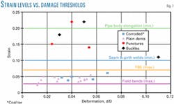
An alternative to dent depth that is gaining acceptance is to make use of the actual dent geometry (as measured in the field or by high-resolution deformation ILI tools) to estimate the strains associated with the dent, since strain is a measure of material damage.
As Fig. 7 shows, dent depth does not correlate to strain, but thresholds for some kinds of failure do correlate to strain. The question is, how much strain is too much?
We know that strain up to 3% is acceptable because that is what is incurred in allowable cold field bends. Evidence is given by the corroded dents that coal tar may disbond at strains of 4-5%.
Test specifications for fusion-bonded epoxy require surviving strains between 2 and 3%, although test straps have been observed showing crack resistance to strains of 7%.
Finally, cracks have been observed in pipeline buckles at strains that are a large fraction of the uniaxial elongation. Hence, a maximum strain of 6% would provide a reasonable factor of safety against metal failure in a restrained dent, with the onus that continued monitoring for corrosion may be necessary in the long-term, depending on coating type.
The ASME B31.8 Code adopts new allowances for strains in deformations up to 6% as an optional alternative to depth-based limits.
Occasionally, rock dents are discovered on pipeline girth or seam welds (Fig. 9). Present ASME code requires such a dent to be repaired. Tests and analyses demonstrate, however, that if a weld is ductile and free of gross defects and the operating pressures are not severely cyclical, the weld can tolerate a dent. The ASME B31.8 Code permits shallow dents in welds of sound quality.
In-line inspection
With encroachment damage, the residual dent may have a depth of as little as 0.5% of the pipe OD. This poses a serious challenge to reliable and consistent detection using geometry-type, in-line inspection (ILI) tools. Sometimes the damage produces a signal that, with experience, can be interpreted as such using magnetic flux leakage or ultrasonic ILI tools.
As an aid to interpretation of possible encroachment-damage indications, the operator should consider:
- Shape. Look for long and narrow aspect ratio, or several parallel or adjacent similar features, and crease-like shape.
- Clock position. Most encroachment hits come from above.
- The physical lay of the pipeline. An indicated "sag bend" where the line crosses flat terrain may represent creases from backhoe scrapes being confused for mild ripples in a field bend.
- Proximity to aboveground features where earthmoving may occur. Nearby road crossings or recent construction are examples.
Rock dents can usually be recognized by size, shape, and position on the pipe. Typical traits include:
- Depth: 2% of the OD or greater.
- Clock position: Most rock-induced damage occurs on the lower half of the pipe.
- Shape: Rounded profile rather than long and narrow.
- Extent: Significant ovality or indentation extending over several feet of pipe.
The data from a high-resolution deformation tool can be used to estimate strain as a way of evaluating the severity of the dent.
Mechanical damage in pipelines is a complex issue. The severity of damage, potential failure modes, and appropriate repair choices all depend greatly on how the damage was introduced.
Encroachment damage presents an immediate hazard potential, whereas construction damage presents a long-term maintenance concern.
The author

Michael J. Rosenfeld is a senior structural engineer and vice-president of Kiefner & Associates Inc., Worthington, Ohio. His expertise includes structural mechanics, stress analysis, component design, and pressure vessel and piping design. He has performed analyses of various types of equipment including pipelines, nuclear power piping systems, suspended conduit systems, pumps, valves, heat exchangers, tanks, instrument racks, generator rotors, aerospace components, and appliances. Rosenfeld is a member of ASME B31.8 Section Committee and B31 Standards Committee. He received his BS in mechanical engineering from the University of Michigan and his MS in mechanical engineering from Carnegie-Mellon University.
Based on a presentation to the API Pipeline Conference, Apr. 9-10, 2002, Dallas.