Shell completes testing of record-setting tie-in plan
Shell’s tie-in of the Perdido oil pipeline in the US Gulf of Mexico is the deepest tie-in ever preformed to an already operating system (5,000 ft). It is also the first to use a prefabricated foundation and jumper. Shell projects Perdido production of 130,000 b/d, with first oil slated for early 2010. This article examines preparation for the foundation and jumper installation.
HOOPS connection
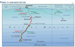
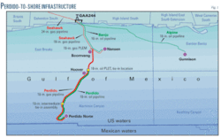
The only path out from Shell’s Perdido development is south through harsh terrain and into a canyon running north. Tie-in lies 200 miles south of Houston. The closest platform is Hoover, 75 miles to the north but lacking large-diameter connections or expansion capacity (Fig. 1).
Tie-in of Perdido is the first deepwater postinstalled subsea connection. It was designed to reduce mainline downtime, allow for future reconfiguration (or disconnection), and use proved components.
Design and installation incorporated lessons Shell learned repairing the Mars pipeline, damaged by an anchor drag during Hurricane Ivan in 2005. Mars repair used dual sleds with a jumper connection. Alignment of the various components, including the large jumper, proved difficult and the project’s gantry system had to be redesigned. Repairs included reinstalling a 3,500-ft section of the Delta 20-in. pipeline system upstream of the MP69 P pump station and reconnecting it to the Odyssey 20-in. line (OGJ, Aug. 22, 2005, p. 75).
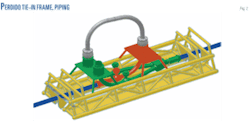
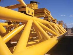
The Perdido connection to the Hoover Offshore Oil Pipeline System (HOOPS) attaches the Hoover pipeline to a smaller jumper which in turn is attached to a piggable Y before reconnecting to the main line (Fig. 2). The other branch of the Y will be used to connect the Perdido line. The frame used (Fig. 3) fixes the alignment of the entire system, allowing the jumper to travel out on the initial mobilization.
Vessel, modeling
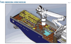
Oceaneering’s Olympic Intervention IV will transport the hardware and tools required for the installation and perform surface duties during the installation. The vessel features a satellite communications system capable of transmitting streaming video for real-time work observation by shore personnel. Olympic Intervention IV also has 1,600 tons deck capacity, 10,225 sq ft of clear deck, a large working moon pool, two Oceaneering work-class remotely operated vehicles (ROV), an on-board ROV tooling suite, a 150 mt capacity crane with active heave compensation, accommodations for 150 persons, a DNV AUTHR (Class 2) dynamic positioning system, and a helicopter platform capable of landing Super Puma and Sikorsky S61 aircraft.
Solid-works three dimensional modeling of the vessel allowed for equipment layout, loadout modeling, and hazard assessment prior to loading (Fig. 4).
Mission simulation
Oceaneering’s Modular Integrated Man-Machine Interaction Control (MIMIC) allowed a wide scope of preinstallation simulation. Beyond building ROV-pilot familiarity with the tools they will be using, flying the vehicle, and observational perspective, simulation with MIMIC—which uses real weights and strains and changeable environmental variables—helped develop installation procedures through pilot testing.
MIMIC provides realistic tension on guidelines and accurate dynamics computation as well as sea-state and environmental conditions. It then uses these data to develop simulations and distributable simulation replays.
Oceaneering initially left pilots to their own means, telling them what was to be done and timing them. Collecting these data added input to the processes actually used during installation.
It can also help fine-tune tools proposed for a given project. If a task is not easily completed in a particular sequence, from a particular direction, or with a particular tool, pilot input can help shape the installation procedure used in the field. Any standard CAD format can create installation models for use in MIMIC.
An inertial navigation system (INS) provides essential ROV behavior data to the MIMIC system. The INS core consists of an inertial measurement unit containing three fiberoptic gyroscopes to give heading information and three accelerometers to monitor changes in acceleration.
MIMIC also contains a video streaming module providing broadband quality on a single 64 kilobyte/sec data line, with no limit on the number of users. The module consists of a video processing computer, which streams the video signal from the operation. The data line then streams the compressed video to an onshore server which transfers the live stream to a password-protected web site for customer access.
Development, tools
Shell developed the Perdido tie-in concept and hired Oceaneering to make it ROV friendly and doable. Shell and Oceaneering used a sample of the actual pipeline already installed for testing of all tools at Arctic Slope Regional Corp. subsidiary Omega Natchiq Inc.’s facilities in New Iberia, La. An onshore run-through of the completion took place in New Iberia Feb. 6, 2009.
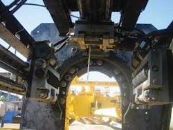
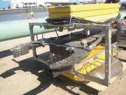
An ROV-piloted FPE-weld seam removal tool rated for 10,000-ft water depths will remove weld seams from the already layed pipe (Fig. 5). An ROV will also deliver a saw attachment with a 60-in. diameter carbide tipped blade (Fig. 6) to the pipe segments needing sawing and clamp it to the pipe, leaving it in place under the ROV pilot’s control while the vehicle itself uses a hydraulic ram to engage the pipe and keep it in place.
Similar saws were used for years nonstop doing offshore salvage and recovery work after hurricanes Katrina and Rita.
An oil containment dome used while this work is under way can capture up to 1,000 bbl of potentially leaked oil and transfer it to a reservoir sitting on the bottom for recovery to surface. A similar dome was developed during Mars repairs to contain an offshore leak in Main Pass 69 near a wildlife refuge.
The ROV cage Olympic Intervention IV lowers from the surface will also carry the ROV’s tools below, allowing the vehicle to move to and from to change tools without returning to the surface. Two ROVs will be operating simultaneously on this job; one working while the other observes.
High-definition cameras will record the entire operation to a hard drive. The cameras allow pilots to pan in much closer than they could with conventional filming technology without actually flying the ROV as close as they once had to.
Two full crews flying 12-hr shifts will be working at any given time during connection installation. Four four-person crews total will deploy, each consisting of a pilot, supervisor, and two technicians.
Hydraulic winches preinstalled on the bottom will pull the 70-ft long foundation down to the pipeline. The foundation will be buoyant. Rather than let the winches hold the load for the project’s lifetime, however, the load will be transferred to pipe hangers, and the winches and other hydraulic components will be recovered to the surface.
