Improved method makes a soft landing of well path
Research and field experience have shown that well-path control is important in many cases, not only to reach the desired coordinates, but also to arrive at the well completion target from the preferred trajectory.
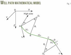
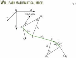
The authors developed an advanced 3D model that employs two arcs in respective planes, separated by a straight section, and base the model on the premise that the arc curvature remains constant in each section (Fig.1).
Starting from a given location, the well path used by the model is the simplest one possible to hit the expected target from a specified trajectory. The method works in an iterative fashion, avoiding a trial-and-error procedure.
The equations are exact, the calculated results are accurate, and the method represents a significant improvement over the traditional well-path planning techniques. The model and formulas were programmed into computer software; the results proved satisfactory for directional and horizontal wells in China.
Accurate well-path planning is the prerequisite for operators to drill directional or horizontal wells successfully. Engineers can plan well paths in a 2D plane, if no special requirements are imposed by either the surface location, underground conditions, or drilling operational considerations.
Circumstances often require that well planners employ 3D well trajectory calculations, however, as highlighted in the following situations.
- The operator must avoid underground obstacles. The surface location may be offset from the target, such as the case with an offshore platform or when other obstacles are present on land.
Also underground obstacles in the vertical plane between the wellhead and the well completion target, such as existing well bores, salt domes, metallic deposits, faults, gas caps, and water cones, will force engineers to employ 3D well trajectories. - The well planner must consider bit walk. Effectively using the natural formation deflection that causes bit walk, engineers can reduce the workload of well trajectory control and drilling cost. They must design the 3D well path, especially in areas where bit walk is considerable.
- The driller must make a path correction. When a well trajectory deviates from the planned path, the correcting section must employ a 3D trajectory to hit the predetermined target. This is similar to a sidetrack or branched well when the target is not in the vertical plane defined by the wellbore direction at the sidetrack or branch point.
- Companies design wells with multiple completion targets. Since the multiple completion targets are not normally in a same plane, drillers must employ 3D well paths to reach the targets successively.
Preferred trajectory
Existing methods for planning 3D trajectories are available, but their objectives are only to hit the expected targets.1-5
In some cases, however, adjusting the trajectory to the preferred direction is more important than only reaching the target. For example, trajectory direction is more important than the wellbore's coordinates in space, when attempting to hit every target in 3D, multiple-target wells.
When drilling horizontal wells, engineers must focus on trajectory direction to land the build-up section successfully and continue drilling the horizontal lateral. The industry has not found a method, however, for planning a well trajectory, from a given starting location, that reaches an expected target from a specified direction.
Generally, drillers use a bent housing motor or other steering equipment, operating in sliding mode, to change well-path direction. The trajectory curvature is regarded as a constant arc in 3D space.
Based on this concept, the authors devised a double-arc model to solve the problem. The method yields a well trajectory that hits the predetermined target from a specified path direction, with no need for trial-and-error procedures.
Model description
Downhole steerable-motors, bent-housing motor assemblies, or downhole motors with bent-sub assemblies make changing the trajectory easy. Industry research and field experience indicates that deflection rates of steerable assemblies, in sliding mode, are essentially constant.
If the build or deflection rate remains constant, the resulting well trajectory is an arc. For this reason, one can represent the well path as a combination of planar turns and straight sections.
The authors considered the path to be drilled as two arcs in their respective planes separated by a straight section, in order to hit a target from a specified direction, from a starting point on an existing well path (Fig. 1). This profile is the most simplistic possible to meet the well trajectory requirements.
Reaching the predetermined target from the specified direction provides five equality constraints as indicated by Equations 1-5 (accompanying box). The problem then becomes finding a set of parameters to satisfy the constraints.
Click here to view Equations
This survey is in PDF format and will open in a new window
The process of finding a solution is not easy. There are many trigonometric functions implicitly involved in the constraints. The unknown profile parameters are not independent, according to the mathematical model of the well path. Solving the problem iteratively often leads to divergent results.
Solution
Directly solving Equations 1-5 is not the only way to satisfy the five equality constraints and find a solution. The authors have found an operative method to solve the problem, dividing it into several steps.
First, one determines the tangential vectors tA and tT of the well path, in terms of the coordinates and directions at the starting point A and the target T. If there is a point D in the reverse direction of the vector tT located a distancearcµ0 to the target, its coordinatesXD , YD , and ZD are defined by Equations 6-8.
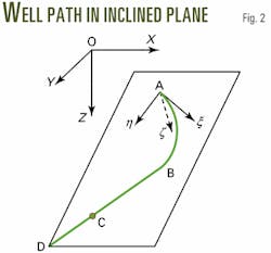
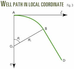
Second, one determines the plane as defined by point D and the vector tA . The well path from the starting point A to point D is designed in this inclined plane, using the method of planning a 2D path.
Also, the term under the square root of Equation 14 must be greater than or equal to zero. To satisfy this constraint, one must select a bottomhole assembly to ensure an adequate deflection rate.
Fourth, Equations 16 and 17 define the inclination aH and the azimuth fH of the straight-line section. Equation 18 gives the central angle over the second arc section. Equation 19 defines the tangent line segment length (CD or DT) of the second µ.This process of iterative calculations yields a value of µthat is closer to the solution than the initial value, µ0. If a pre-selected tolerance e is given, Equation 20 provides a conditional statement for a pre-selected tolerance of e. If this conditional is not met, let µ= µ0, then repeat the above procedure until the prescribed tolerance is reached.
Finally, the primary parameters of well path are determined. Equations 21-23 define the well-path lengths, including the first arc DL1, the straight (hold) section from point B to point C (DLH) and the second arc DL2.The value of C in Equations 21 and 23 depends on the units of q1 and q2 (C = p1/180 if the angle is in degrees, or C = 1 if the angle is in radians).The procedure just outlined provides a solution, even though Equations 1-5 were not solved directly. The conditions were distinctly satisfied and the method provides excellent astringency and stability of calculation.
Trajectory calculation
Trajectory calculations provide descriptive parameters at any point along the well depth as independent variables.
These parameters are the inclination a, the azimuth f, the rate of inclination change ka, the rate of azimuth change kf, the coordinates X, Y, Z, the horizontal displacement S, and the azimuth of horizontal displacement fS.The well-path profile consists of two arcs and a straight line. The straight section is relatively simple and does not warrant a detailed description.
Although the industry has had a well-path arc model for many years, the values of a and f on an arc section have only been calculated approximately. No previous mention was made of how to calculate ka and kf.To provide a general description of the arc sections, Equations 24 and 25 first define the tool face angles. For the first arc section, the formula of coordinate conversion between A - xhz system and O-XYZ system is given in Equation 26.Equations 27-30 express the inclination, the azimuth, the rate of inclination change, and the rate of azimuth change on an arc section.6 7 Substituting matrix elements Tij into Equations 27-30 yields Equations 31-34, which are used to calculate the above parameters explicitly.
After calculating the first arc and straight-line sections, one can determine the parameters at point C. One can then use Equations 26-34 to calculate the parameters for the second arc. Subscripts C and 2 replace the subscripts A and 1.
One can use Equation 13 to calculate the coordinates of the arc sections. In this case, the subscripts C and T should replace A and D in Equations 9-13 for the second arc section and the subscripts in Equations 31-34 also need to be replaced with appropriate parameters.
In addition, researchers have verified that Equations 29-30 and 33-34 satisfy Equation 35, the equation for borehole curvature presented by G. J. Wilson.8
Researchers have implemented these procedures using a computer program, demonstrating that it works very well.
Example
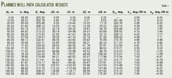
An operator plans to drill a horizontal well with an inclination of aT = 90° and an azimuth of fT = 308°, at the completion target.Assume that drilling operations are underway. At the tool face, the current inclination is aA = 58° and the azimuth is fA = 300°. To reach the target, the rig must drill an additional 57-m vertical depth and 170-m horizontal displacement, with an azimuth of 315°.The engineer must plan the well path to hit the target from the predetermined direction. To start, he will assume the deflection tools have been selected with a curvature or build rate of 8°/30 µ(k1) for the first curve section and 10°/30 µ(k2) for the second curve section.From known data, the requirements above, and iterative calculations, Equations 6-20 yield q1 = 26.06°, q2 = 24.26°, and µ= 36.94 m. Equations 21-23, applied individually, yield the lengths of the first arc section DL1 = 97.72 m, the straight section DLH = 12.09 m, and the second arc section DL2 = 72.78 m.Equations 24 and 25 calculate the tool face angles of each arc section. The tool face of the first arc section is w1 = 63.60° and of the second arc section is w2 = 316.43°. These are the tool face angles at the start of each arc section, since the tool face changes along the 3D arc trajectory.References
- McMillian, W. H., "Planning the Directional Well-a Calculation Method," J. Pet. Tech., June 1981, pp. 952-62.
- Planeix, M. Y., and Fox, R. C., "Use of an Exact Mathematical Formulation to Plan Three Dimensional Directional Wells," SPE Annual Technical Conference, Sept. 23-26, 1979, Las Vegas.
- Xiushan, L., Tongci, Q., et al., "Design of a 3D Drift Well-Path," Acta Petrolei Sinica, Beijing, Vol. 16, No. 4, 1995, pp. 118-24.
- Suryanarayana, P. V. R., McCann, R. C., and Rupani, R. A., "Mathematical Technique Improves Directional Well-Path Planning," OGJ, Aug. 24, 1998, p. 57-63.
- Guo, B., Miska, S., and Lee, R. L., "Constant Curvature Method for Planning a 3-D Directional Well," SPE Rocky Mountain Regional Meeting, Casper, Wyoming, May 18-21, 1992.
- Xiushan, L., Jun, G., "Description and Calculation of the Well Path with Spatial Arc Model," Natural Gas Industry, Beijing, Vol. 20, No. 5, 2000, pp. 44-47.
- Xiushan, L. et al., "Designing Theory and Describing Method for Wellbore Trajectory," Heilongjiang Science and Technology Press, Harbin, China, 1993.
- Wilson, G.J., "An Improved Method for Computing Directional Surveys," J. Pet. Tech., Vol. 20, Aug. 1968, pp. 871-76.
The authors
Xiushan Liu is a senior engineer at Sinopec Corp.'s Exploration & Production Research Institute in China. He has a BS and an MS from Daqing Petroleum Institute and a PhD from Research Institute of Petroleum Exploration & Development of CNPC, all in petroleum engineering. His professional experience includes work as an associate professor at Daqing Petroleum Institute and as a postdoctoral fellow at Tsinghua University.
Zaihong Shi is reading for her PhD at the Institute of Mechanics of the Chinese Academy of Sciences in China. She received her BS and MS in petroleum engineering from Daqing Petroleum Institute. Her professional experience includes work as an associate professor at Daqing Petroleum Institute and Tsinghua University.
