World's largest N2-generation plant starts up for Cantarell reservoir pressure maintenance
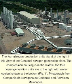

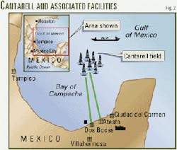
In May 2000, the first of four 300-MMscfd cryogenic process units was commissioned on schedule in the nitrogen-generation plant (NGP) for the Cantarell field off the Atasta Peninsula, state of Campeche, Mexico (Figs. 1 and 2).
In June 1996, Bechtel Corp. and Bechtel affiliate IPSI LLC (IPSI) proposed using nitrogen injection at the field for reservoir pressure maintenance following an extensive study of available alternatives.
In February 1997, Pemex Exploración y Producción (PEP) published an international invitation to bid under a "build, own, and operate" agreement to develop a privately held project to supply 1.2 bscfd of nitrogen for injection.
Upon full commissioning in December 2000, the NGP71 more than doubled the world's existing N2-generating capacity. Bechtel in association with Petróleos Mexicanos (Pemex), as overall Cantarell project management contractor, also managed this engineering, procurement, and construction package.
Under the procedures selected for this bid, the contract was awarded in October 1997 to Compañia de Nitrógeno de Cantarell (CNC) to construct, operate, and maintain the plant and supply nitrogen to the field injection sites for 15 years.
CNC is an international consortium of five companies (BOC Gases, Marubeni Corp., Westcoast Energy, ICA Fluor Daniel, Linde) with BOC Gases as consortium leader.
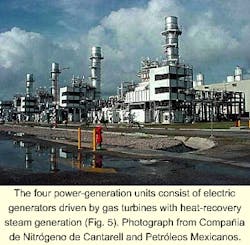
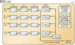
The overall NGP42 on 30 hectares includes four parallel process units, each generating 300 MMscfd of high-purity nitrogen (Figs. 3 and 4), and three power-generation units consisting of electric generators driven by gas turbines, each connected to a heat-recovery steam generation system (Fig. 5).
A fourth power-generation unit, to serve as a full spare, improves the overall on stream factor of the NGP.
An open cooling-water system recycling seawater combines with a closed freshwater cooling system to provide cooling for the entire plant. The overall plant cooling duty is roughly 2,800 MMbtu/hr.
Total horsepower for air and nitrogen compression exceeds 500,000 hp. The overall nitrogen recovery exceeds 90%. The waste stream, which contains more than 70% oxygen, is vented to the atmosphere.
The nitrogen product is compressed to 1,685 psia at Atasta, then routed 53 miles offshore through two 36-in. OD pipelines for injection into the crown of the gas cap. The nitrogen injection platform is a seven-well, eight leg drilling platform. The injection wells are 95/8 in. diameter, approximately 4,600 ft deep.
Oil production
By law, Pemex, through PEP, owns all hydrocarbon reserves in Mexico. PEP also operates the Cantarell field, the most important oil field in Mexico and the sixth largest in the world.
Discovered in 1978, Cantarell consists of four blocks: Akal, Nohoch, Chac, and Kutz. The Akal block is the most important, containing 91.4% of the 35 billion bbl of original oil in place (OOIP).
Production started in June of 1979 and peaked at nearly 1.2 million b/d in April 1981 through 40 wells. This production level was sustained until early 1996 through the drilling of 139 development wells that used gas lift and reduced back-pressure restrictions.
Currently, the field is producing 42% of national production and contains 25.7% of Mexico's oil reserves. The oil produced from this field is Maya type, 19-22 degrees API.
Akal is a fractured carbonate reservoir with no original gas cap and original reservoir bottomhole pressure (BHP) exceeding 3,800 psia at the oil column datum.
Soon after production from the field started, the BHP at the top of the structure dropped to less than the bubblepoint of 2,128 psia and a secondary gas cap formed. The Akal field has high permeability due to extensive fracturing, a thick (more than 3,000 ft) reservoir section, and high structural relief.
These factors, plus formation of the secondary gas cap, make for an efficient gravity-drainage recovery mechanism.
By 1996, after 17 years and more than 5 billion bbl of cumulative production, the reservoir pressure had declined 60% to less than 1,520 psia at the oil column datum. Well productivity had also fallen to 25%.
This decline contributed to numerous operational difficulties in sustaining target oil production rates (for example, falling well fluid levels, increased need for gas lift, and the constant need to lower the gas-lift valve settings).
More importantly, it was determined that if reservoir pressure were not stabilized, vast amounts of oil would remain unrecoverable at the end of the economic field life.
Modeling efforts predicted that the incremental recoverable reserves associated with pressure maintenance, combined with the planned drilling and other developmental activities of the overall Cantarell infrastructure upgrade program, would be 2-3 billion bbl.
When PEP decided to commission a study of general Cantarell complex infrastructure upgrade requirements in early 1996, reservoir pressure-maintenance techniques were key.
Pressure maintenance
Pressure maintenance is needed for several reasons:
- As stated, reservoir BHP has fallen from the original pressure of 3,800 psia to the current pressure of 1,520 psia, a 60% reduction.
- Fluid levels in the wells continue to decline, resulting in reduced oil producing rates per well. There is less vertical liquid head to facilitate gravity drainage.
- Gas-lift volumes must be continually increased to sustain oil production targets.
- Gas-lift valves could be moved to lower levels in the wellbores to sustain oil production rates. Because valve depths were already at 4,000-5,600 ft subsea, however, this could not be continued indefinitely.
- Gas-injection pressure maintenance may be necessary to impede the oil-water contact (OWC) migration so that the water in the southern part of the field will not progress over the central structural highs into lower levels of the northern portion of the field.
- The Akal field has favorable conditions for an effective gravity-drainage recovery mechanism; that is, high permeability due to extensive fracturing, a thick reservoir section, high structural relief, and formation of a secondary gas cap.
Types of pressure maintenance
PEP looked at two options for pressure maintenance: water injection and gas injection.
- Based on water-production information, the OWC was encroaching upon the southern part of the Akal field.
Originally it was at a depth of 10,500 ft subsea and had risen to 9,000 ft and, in some places 8,000 ft subsea in sections of the southern part of the Akal field.
Since there is currently no water in the northern part of Akal, there was a major concern in preventing water movement from the southern part into the northern part of the field. In addition, many wells in the northern section of Akal are completed below the current OWC in the southern part.
The fractured nature of this field precluded water injection because it could channel through fractures and fault systems to the northern part of the field, resulting in the premature watering out of some producing wells.
This is due to the "fingering phenomenon," in which water may preferentially reach the well before the oil, thus resulting in premature "watering out" of the producing well.
Akal is a highly fractured and faulted reservoir, which increases the likelihood of water fingering and reduces the recoverable reserves.
Pemex reservoir engineers and consultants' analysis estimated that water fingering could reduce the ultimate oil recovery from Akal by 15 to 20% of OOIP.
- Pressure maintenance through the injection of gas is widely used in many large oil fields. Among the largest is Prudhoe Bay where natural gas is currently being injected at rates four to five times greater than the volume of nitrogen to be injected into the Cantarell field.
Other large fields currently utilizing gas injection for pressure maintenance include Fateh in Dubai, Fahud in Oman, Ekofisk off Norway, Hassi Messoud in Algeria, and Hawkins and Yates in the US.
Gas injection is considered more effective than water injection in preventing water movement into the northern portion of the Akal field. Gas injection takes advantage of the gravity-drainage recovery process of the field.
Water-drive recovery efficiency is approximately 40-45% of the OOIP, while gravity-drainage recovery efficiency is approximately 55-60% of OOIP.
Thus, gas injection has more favorable efficiency compared to water injection for a gravity-drainage recovery scheme and will increase oil recovery by approximately 15-20% OOIP.
These reasons recommended use of gas injection for pressure maintenance.
To verify the suitability and design parameters for gas injection at Akal, PEP conducted a gas-injection test in the Cantarell field.
This test confirmed the number and locations of new injection platforms required to carry out the gas-injection program, including necessary wellhead injection pressure, the directions and angles of all new wells, along with other relevant data.
Types of gas injection
Among the major gases used in gas injection are natural gas (dry, sweet, mostly methane), carbon dioxide (CO2), flue gas (exhaust from power plants, gas turbines, gas engines or heaters), nitrogen (N2), and associated gas (wet, sour, produced gas).1 3 5
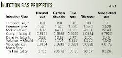
Injection gases must displace the oil at the gas cap conditions which for the worst case scenario is at approximately 1,520 psia and 190-220 degrees F. Table 1 lists the properties of the various injection gases at conditions existing at the top of the gas cap.6
Natural gas
Before 1970, natural gas was the primary injection medium used to maintain reservoir pressure. Afterwards, natural gas became unavailable in some areas as well as too expensive to be used for reinjection. It is still being used when there is no economical way to recover natural gas for sales.
Dry, sweet natural gas is noncorrosive and has no deleterious effects on the field. PEP's calculations of the injection-volume requirements between dry gas, associated gas, and nitrogen indicate that 10-20% more natural gas or produced associated gas would be needed to achieve the same reservoir displacement volume compared to nitrogen.
At the downhole pressures in the Akal field, both natural gas and nitrogen are immiscible with the oil.
Moreover, as projections show a strong demand for natural gas across Mexico, reinjecting some of this gas could hinder the growth in other parts of the national economy.
If natural gas is not used, the net produced associated gas from the field can be sold, resulting in increased revenues from the field.
Carbon dioxide
Carbon dioxide (CO2) is used in miscible flooding where its low miscibility pressure lowers the viscosity of the heavy oil and causes swelling of the oil, leading to increased or enhanced oil recovery (EOR).
In the Akal field, the pressure is low enough that even CO2 would not be very miscible with the oil. In this instance, therefore, pressure maintenance to improve gravity drainage of the field is the dominant objective.
CO2 is used in the US because of the availability of large natural reserves and tax subsidies dating back to the energy crisis.
The CO2 is collected from reservoirs and transported by pipelines to the injection wells. When CO2 reserves are available locally, the production costs of CO2 are low. Unfortunately, there are no large reserves of naturally occurring CO2 near the Cantarell field.
The only method of producing CO2 would be to remove it from turbine exhaust or flue-gas streams, a complex and expensive process.
First, the flue gas must be generated either by heaters, gas engines, or gas turbines. Then it is cooled, followed by removal of impurities such as NOx and SOx. The flue gas is slightly compressed and fed to an acid-gas-removal unit where the CO2 is separated at low pressure.
The presence of O2 in all flue gases significantly increases the operating difficulty and cost for these types of acid-gas removal plants. In fact, only two types of chemicals have been used successfully in this application: inhibited monoethanolamine and sterically-hindered amines.
The CO2 is then dried in a triethylene glycol unit and the product CO2 compressed and transported in a pipeline to the injection platform. If the CO2 is not completely dry, there will be significant corrosion problems in the gas handling and gas-injection systems as well as in the injection wells.
As can be seen in Table 1, CO2 has a much lower compressibility factor and higher density than the other gases. That is, more standard cubic feet of CO2 must be generated to get the same quantity of displacement gas in the reservoir.
This will result not only in a larger CO2 plant but more injection wells with larger tubulars. It might even require additional injection platforms.
CO2 is slightly miscible at these pressures and could therefore lead to earlier breakthrough into the associated gas than nitrogen. It is also known to cause asphaltene precipitation in the reservoir, which could lead to formation plugging.
Even though the CO2 is dry, it will pick up moisture in the reservoir and increase the possibility of corrosion in the oil production equipment. In addition, as the CO2 breaks through in the oil and then appears in the associated gas, it will increase the produced gas that must be treated to remove the CO2 prior to sales.
Due to the extremely corrosive conditions existing in a CO2-generation plant, it will experience a lower on stream factor than a nitrogen generation plant.
Flue gas
Flue gas is used in miscible and immiscible flooding instead of hydrocarbon gas injection. It would be more economical than hydrocarbon gas, especially if it can be obtained easily from combustion sources such as power plants, gas turbines, gas engines, or heaters.
Flue gas can be quite corrosive, however, because it contains NOx, SOx, CO, CO2, H2O, and O2. Other oil fields that have used flue gas for pressure maintenance have encountered corrosion problems, leading in some cases to the abandonment of the process.
At a minimum, the flue gas should be dry. Corrosion problems in the production equipment can happen, however, where other components in the flue gas come in contact with water in the reservoir.
In order to avoid corrosion and problems in the injection and production equipment, all of these impurities must be removed from the flue gas. This is particularly true of O2, which can damage the reservoir. The result is a complex and expensive plant.
As with CO2, flue gas is slightly more miscible than pure nitrogen and will therefore break through into the associated gas sooner than nitrogen. The cost of removing the CO2 and N2 from the produced sales gas would have to be added to the total cost at some point in the future.
The nitrogen-rejection studies of Bechtel/IPSI estimated that these facilities would add about $0.04/mcf to the flue gas cost. It is also noteworthy that most, if not all, operating flue gas plants have been converted to N2 only.
Nitrogen
Nitrogen has been used successfully for more than 20 years in pressure maintenance and enhancing reservoir-drive mechanisms for both miscible and immiscible projects. It is immiscible in the Akal reservoir.
As shown in Table 1, it provides a higher reservoir displacement volume per standard volume of nitrogen than any of the other injection gases, that is, lowest volume requirement for pressure maintenance.
The nitrogen sent to the field for injection has a purity of less than 10 ppmv oxygen. At this concentration O2 will not react with the reservoir fluids or compressor lube oils to produce undesirable by-products and precipitates.
Moreover, the formation of anaerobic material in the formation is minimized, thereby reducing the need for biocide inhibitors.
Nitrogen is also noncorrosive. Therefore, no special metallurgy is required for the injection equipment, no corrosion inhibitors need be added to protect the existing equipment, and no materials must be replaced on the existing production equipment.
Nitrogen is environmentally acceptable and does not contribute to the greenhouse effect when rejected and released to the atmosphere.
It is also readily available from air, and a plant can be located almost anywhere. Nitrogen production by cryogenic air separation has been a proven technology for more than 80 years.
Because of the inert and noncorrosive nature of nitrogen, on stream availability for these plants ranges from 95-99% including down time for scheduled maintenance. This makes nitrogen a reliable source as a pressure-maintenance injection gas.
The use of nitrogen as injection gas instead of associated natural gas frees additional gas for sale. For some reservoirs, water injection may be required for reservoir-mobility control. A single distribution-injection system for both nitrogen and water can be used because the cryogenic nitrogen is bone dry when it is produced from the NGP and will remain inert if water is reintroduced.
Eventually, nitrogen will break through into the produced associated gas. A nitrogen-rejection plant will then be needed to ensure that the product gas is marketable. This breakthrough generally occurs later than if CO2 had been used.
Based on Bechtel/IPSI nitrogen rejection studies, these facilities would add about $0.05-0.06/Mcf to the cost of nitrogen. This is based on building the nitrogen-rejection facilities at the present time.
However, these facilities would not be needed until 5 to 10 years after injection commences. The present value cost of this facility would be even less.
Even with the added cost for future nitrogen-rejection facilities, the nitrogen-injection option is still less expensive than injection of any other kind of gas.
Associated gas
The maximum volume of associated natural gas produced by the Cantarell complex is less than the maximum volume required for pressure maintenance of the field.
Thus, in addition to the volume of Cantarell associated gas that would be available for reinjection, massive additional volumes of natural gas would have to be transported to the field in order to sustain full pressure maintenance.
Furthermore, the cost for this produced associated gas is about three to five times the cost of nitrogen.
Economics; production specification
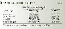
Bechtel/IPSI studies determined the relative costs of the gas-injection systems (Table 2).4 5 7 The estimated compression horsepower is based on compressing the feed to the necessary processing pressure and the product gas to the necessary delivery pressure.
In other words, the estimated horsepower including all compressing horsepower.
According to the contract signed with CNC, PEP will receive at the injection platform up to 1.2 bscfd of nitrogen for 15 years. The cost of nitrogen will consist of fixed costs based on production capacity, operation and maintenance costs, and a variable cost depending on fuel consumption.
The nitrogen-injection program, from generation of the nitrogen through ultimate injection into the reservoir, required certain facilities to be owned and operated by PEP, as well as other facilities to be owned and operated by CNC, the supplier, under the build-own-operate contract model. These elements are now briefly described.
The CNC-owned portion of the project consists of four major elements: production of nitrogen (NGP), supply of power, associated supply and delivery pipelines, and site preparation and infrastructure requirements.
In other words, CNC is responsible for everything inside the boundary limits of the NGP. This consists primarily of atmospheric air pretreatment and compression, cryogenic nitrogen production, and product nitrogen compression, along with associated power generation, cooling facilities, and other utilities and infrastructure activities necessary to support the facility.
The CNC scope also includes two 36-in. OD subsea nitrogen-delivery pipelines. The first is approximately 56 miles long, connecting the nitrogen plant to a PEP-owned nitrogen injection platform offshore Bay of Campeche within the Cantarell complex.
There is also a nitrogen pipeline lateral, approximately 10 miles long, which connects the nitrogen plant to a PEP-owned nitrogen delivery pipeline inside the boundary limits of the Atasta compressor station.
Furthermore, it also includes a 12-in. OD fuel-gas pipeline, approximately 10 miles in length, which carries natural gas from the PEP master pipeline within the Atasta Station to the nitrogen plant, as well as the lines required for the suction and discharge of cooling water. CNC has the responsibility for the operation and maintenance of all above facilities throughout the life of the contract.
The PEP-owned facilities required to complete the nitrogen-injection loop, which are addressed under separate EPC contracts, consist of one 36-in. OD nitrogen-delivery pipeline, one nitrogen-injection platform, and seven nitrogen-injection wells.
Specifically, the NGP has the following specification requirements and limitations:
- Capacity: 1.2 bscfd.
- Delivery pressure: 1,685 psia (maximum), 1,385 psia (minimum) at the boundary limits (Atasta) and 1,605 psia (maximum), 1,305 psia (minimum) at the injection platform.
- Delivery temperature: 140 degrees F. maximum (60 degrees C., maximum). This temperature is limited by the pipeline wrapping and reservoir.
- On stream factor: 95%. Additional power-generation unit is required to meet the on stream factor.
- Individual train performance test for 72 hr and full facility performance test to verify the results for 7 days.
- Gas turbine site rating: 91.4 degrees F.
The key factors considered in the selection of equipment to optimize the operating and total installed costs of the facility included:
- Maximizing the on stream availability of the plant, considering the remote site location.
- Physical restraints on the equipment sizing to allow transportation to the site from Europe, the US, and Mexico.
- Limitations imposed on size scale-up and equipment operating history to comply with the technical requirements contained in the bidding guidelines.
*Local weather conditions, including average temperature, relative humidity, and the proximity of a marine environment.
- Lack of a freshwater supply in the area.
The amount of oxygen remaining in the cryogenic nitrogen is usually dictated by customer requirements. The nitrogen product from NGP must contain less than 10 ppmv oxygen and 0.5% maximum total of all other contaminants (CO2, CO, NOx, and SOx) due to the following:
- O2 and H2S can react in the reservoir to produce solid sulfur, potentially plugging the producing and injection wells.
- O2 produces sulfate reducing and other bacteria that can result in severe corrosion and reservoir plugging. Historically, this has been controlled with the injection of biocides and corrosion inhibitors, adding to the operating cost, especially offshore.
- O2 can react with N2 to produce NOx, which then combines with water to produce concentrated nitric acid which is very corrosive. For example, 1 MMscfd of gas combined with 10 ppmv NOx will produce 1.5 lb of concentrated nitric acid.
- O2 can oxidize compressor lube oil, also resulting in solid combustion products in the injection wells.
Moreover, all of these problems are cumulative with time and thus require continuous mitigation, the necessity of which can be minimized or eliminated by minimizing the O2 specification.
One of the main reasons cryogenic nitrogen plants are replacing the use of flue gas as the preferred method for pressure maintenance is the 1-10 ppmv O2 that can be obtained from this process with only a marginal cost increase.
The nitrogen product stream from a cryogenic plant may contain 0.1-0.2% argon and traces of neon and helium. CO2 and water content are essentially nil.
For all practical purposes, therefore, the product may be regarded as 100% pure nitrogen. This pure nitrogen will absolutely minimize or totally eliminate any reaction between O2 and H2S or O2 and N2. Furthermore, the Cantarell reservoir temperature is only about 190 degrees F. This low temperature will make these reactions negligible.
Acknowledgment
The authors thank Antonio Acuña, Tomás Limón, and Armando López-Cerón from Pemex, Ronald Kettles, John Morrison, and Edward Murphy from Bechtel Corp. for their support and assistance for the article.
References
- Kosowatz, J., "Giant Nitrogen Plant Enhances Oil Production Mexico," Engineering News and Record, May 8, 2000.
- Kirtley, J., "Nitrogen From Cryogenic Air Separation Process to be Used for Pressure Maintenance and to Enhance Recovery at Cantarell Complex in Campeche Bay, Mexico." Offshore Technology Conference, Houston, May 1999.
- Barstow, W.F., and Hendricks, H., "Engine Exhaust Inert Gas system for Secondary Oil Recovery," ASME 75-DPG-3, April 1975.
- Kuehm, H.G., "Hawkins Inert Gas Plant: Design and Early Operation" SPE paper 6793, October 1977.
- Wilson, Keith, "Enhanced recovery inert gas processes compared," OGJ, July 31, 1978, p. 162.
- Jain, P., Kuo, J.C., Hernandez, M., Garza, G., Hernandez, T.L., "Offshore Gas Sweetening and Acid Gas Injection: An Overview," University of Oklahoma Laurence Reid Gas Conditioning Conference, Norman, February 2000.
- Limon-Hernandez, T., DeLaFuente, G., Garza-Ponce, G., Monroy-Hernandez, M., "Overview of the Cantarell field Development Program," Offshore Technology Conference, Houston, May 1999.
The authors

J.C. Kuo is technology manager for IPSI LLC, Houston, an affiliate of Bechtel Corp., and has been process manager for the Pemex Cantarell project. He has more than 25 years' experience in gas processing, gas treating, and LNG. Kuo holds a BS from Chung Yuan Christian University, Taiwan, and an MS from the University of Houston, all in chemical engineering. He also holds an MS in environmental engineering from Southern Illinois University, Carbondale.

Javier Luna-Melo is Pemex Exploración y Producción (PEP) supervisor in residence for the nitrogen-supply project. Since 1995, he has been working for Pemex, first within the planning office at Pemex Gas & Basic Petrochemicals (PGPB) and later in PEP. In 1997, he was transferred to the Cantarell project. He holds a BS in petroleum engineering from the University of New Mexico, Albuquerque, and an MS (1981) in petroleum engineering at the University of Texas at Austin.

José B. de León Pérez is constuction manager for the Cantarell project of Pemex Exploración y Producción, Villahermosa, state of Tabasco, México. He worked at the Instituto Mexicano del Petroleo (IMP) for 13 years, joining PEP in 1983. De León Pérez holds an honors degree in chemical engineering from the Universidaad Nacional Autónoma de México in México City and is a member of SPE.

Douglas G. Elliot is president, chief operating officer, and co-founder of IPSI LLC. He has been a member of the Gas Processors Association research steering committee since 1972. He holds a BS from Oregon State University and MS and PhD degrees from the University of Houston, all in chemical engineering. Elliot is a fellow of the American Institute of Chemical Engineers, and a Bechtel Fellow, the highest honor Bechtel offers for technical achievement.