Analysis of tank failure reveals oversight in inspection procedures
Philip E. Myers
Chevron Research & Technology Co.
Richmond, Calif.Gregory M. Mulvany, Ndoma Ntela Chevron Overseas Petroleum Inc.
San Ramon, Calif.
Postfailure inspection of a crude storage tank showed microbial-induced corrosion to be the cause of the leak. Analysis of the incident revealed weaknesses in the company's tank-inspection program that, if corrected, may prevent such failures in the future.A case study of a 10,000-bbl spill from a crude oil storage tank in Africa illustrates the importance of implementing effective inspection practices and using current technologies.
An internal inspection performed 8 months before the spill was not effective in identifying major defects in the tank bottom.
A postfailure inspection revealed microbial-induced corrosion (MIC), which requires special inspection and treatment measures. An analysis of this incident resulted in a set of recommendations for preventing such failures.
The incident
In July 1995, a major spill occurred without warning from the bottom of a 300,000-bbl crude oil storage tank. The spill occurred while the tank was being filled. An estimated 10,000 bbl of oil were lost in less than 1 day.
The spilled oil was contained within the tank berm and recovered. Most of the oil in the tank was quickly pumped to a waiting tanker.
The tank was drained, isolated, cleaned, and prepared for entry. The operator had to perform a difficult and potentially hazardous repair before returning the tank to service.
About 8 months before the spill, the tank had been removed from service for a 10-year internal inspection in accordance with API Standard 653. The inspection was conducted by a reputable inspection agency headquartered in the U.S.
After minor repairs, the tank was returned to service in late January 1995.
The tank
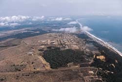
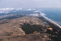
The tank involved in this incident is one of nine large tanks supporting offshore oil production in the area. The 211-ft diameter, 300,000-bbl crude oil storage tank was built in 1967 to the standards applicable at the time.
The tank has an external floating roof and a cone-up bottom built on a concrete ringwall. The tank bottom and lower 2 ft of the shell are internally coated with a thick-film, fiber glass-reinforced plastic (FRP) lining. The tank has an internal sump near its perimeter. The sump is 12 ft in diameter and 5 ft deep.
The leak
In July 1995, an operator was preparing to gauge the tank before pumping it down when he observed oil seeping from the ground. The oil was flowing underneath the tank bottom, percolating through the soil under the ringwall, and bubbling up beyond the tank perimeter. Oil was seeping from the ground along a 30-ft section of the tank perimeter, and as far out as 30 ft from the tank.
A subsequent internal examination of the tank showed that the sump was the source of the leak. A 2-in. hole was found in the middle of the sump wall.
Hammer testing revealed two additional areas, each about 1 ft in diameter, in which the steel had corroded away completely. A follow-up inspection revealed several smaller areas around the sump that were corroded to the same extent.
The FRP lining alone had been holding the tank contents. Hydraulic pressure finally caused the fiber glass coating to rupture.
The repairs
The repairs required to return the tank to service included:
- Removing the sump and surrounding bottom plates
- Excavating the oil-saturated soil
- Adding and compacting new fill for the foundation
- Pouring a 4-in.-thick concrete spacer on top of the existing floor to isolate the new floor from the soil and prevent MIC of the new steel (The alkali content in the concrete acts as a barrier, preventing bacteria from attacking the steel.)
- Casting leak-detection grooves into the spacer to provide early warning of leaks
- Installing a new double bottom on top of the concrete spacer
- Raising the nozzles, door sheets, and other appurtenances
- Installing a new thick-film FRP tank lining.
The cost to clean and repair the tank was $2.3 million-$300,000 more than similar work done in the area. The additional costs were attributable to cleanup, bottom plate and sump removal, and associated foundation work.
The added expenses would not have been necessary had the need for repairs been identified during the 10-year inspection.
Prefailure inspection
In late 1994, the operator performed an inspection based on guidelines prescribed in the 1991 version of API Standard 653.1 API 653 is a performance-based standard that provides criteria and guidelines for compliance, but does not dictate how inspections must be performed.2
The 1994 inspection program for crude oil tanks was a 10-year follow-up to a similar program executed in 1985. The operator elected to use statistical sampling, which is common industry practice.
Before establishing the inspection program, the operator reviewed the inspection practices of other companies, discussed alternative programs with several inspection contractors, and reviewed the recommendations in its company tank manual.
In order to randomly spot-check the bottom, the FRP lining must be removed and replaced. The lining was determined to be in excellent condition. Because replacing it would have cost $750,000, the operator decided to limit the scope of bottom sampling to 21 locations in order to reduce downtime and coating repair costs.
Each inspected area covered about 1 sq ft. This limited inspection revealed no significant corrosion, nor any other condition that indicated the need for additional testing.
The operator's inspection program did include two important requirements that might have prevented the leak if any problems had been found during inspection. These requirements are:
- If any corrosion is detected, additional locations must be inspected to ensure representative sampling of the tank bottom.
- If coating breakdown or failure is detected, the affected areas must be cleaned and inspected.
There are two other considerations that explain why the operator did not perform a more thorough inspection:
- The operator's historical inspection records did not indicate that bottom-side corrosion would be encountered. The only previous indications of floor corrosion were incidents of top-side or internal corrosion related to the material stored in the tank. The FRP lining had been applied in 1985 to provide additional protection from this type of corrosion.
- At the time of the 1994 inspection, the operator considered using magnetic flux exclusion (MFE) scanning. The method was deemed impractical, however, because it had not been proven to penetrate the 1/4 to 3/8-in. thick FRP linings. The operator's tank manual stated that MFE scanning was limited to analysis of "thin-film coatings that are in good condition."
Follow-up inspection
After the leak was detected, visual inspection of the FRP lining showed that it was still in excellent condition. This is typical of a properly applied lining, even after many years of service.
Coupon samples cut at various points on the tank bottom showed severe localized pitting on the underside of the floor plate. These areas of pitting were distributed irregularly around the tank bottom.
A second inspection company performed another inspection through the FRP lining. This firm used MFE scanning to examine the tank floor. The MFE equipment used to perform this inspection incorporated new technology and high-power magnets.
The MFE inspection revealed numerous areas of active, bottom-side corrosion. Many areas showed metal loss of more than 60%, and some had experienced total metal loss. The MFE inspection also revealed many areas with no corrosion, including all the locations inspected previously.
Subsequent analysis of the corrosion under the tank bottom indicated that the source was MIC. This conclusion was supported by laboratory analysis of the floor plate and of soil samples taken from underneath the tank.
The corrosion was caused by bacteria in the soil under the tank. This MIC pattern recently was confirmed on the underside of two adjacent tanks in the same storage area.
Lessons learned
The 1994 inspection of this tank failed to prevent the leak because of a combination of circumstances, including MIC and the use of random sampling. As a result of the tank failure and subsequent investigation, the operator now requires that the internal inspection include an MFE scan of all tank bottoms that contact soil.
In addition, all sumps must receive complete ultrasonic thickness (UT) or MFE inspection. And precautions are taken to keep rainwater out of sumps during inspection.
Some key points learned from reviewing this incident are:
For inspection of this tank, the FRP lining was removed from only 21 locations, or less than 0.1% of the 40,000 sq ft floor area. To provide a reasonable representation of the floor's condition, the number of samples should have been much greater, which would have increased lining removal and repair costs. This makes MFE inspection a much more cost-effective inspection tool.
Random sampling may be appropriate for double-bottom tanks with concrete spacers, or for tanks with well established pitting rates and corrosion patterns. But, because of this incident, the operator no longer recommends random sampling for tanks that rest directly on soil where corrosion patterns are not well established and MIC may be involved.
There is, unfortunately, no practical method of predicting the extent of corrosion caused by soil bacteria. But, because most underside pitting is localized and nonuniform, identifying the corrosion mechanism is less critical. The cost of MFE scanning is not significantly greater than that of coupon cutting and repair. For this reason, MFE is recommended for tanks with the high-risk attributes described previously.
The best approach is to scan the bottom using MFE, and use UT for follow-up and detailed analysis. This is an efficient, thorough method, and has much higher probability of detecting flaws. In addition, there is less need to cut coupons for tank-bottom inspection.
All sumps are subject to high corrosion rates. Sumps collect water and debris, which attack inner coatings and accelerate corrosion; in addition, their undersides are in extremely wet conditions that also accelerate corrosion. Sumps should therefore always be inspected during internal inspections.
When they are lined with a thick-film liner, sumps should be inspected in one of two ways. Either a grid pattern should be inspected using spot UT on 6-12 in. centers, or MFE scanning should be used.
API 653 provides an inspection checklist in Appendix C.3 This list is generally complete, but it lacks any reference to sumps.
This problem has been reviewed by the API Tank and Pressure Vessel Subcommittee, which agrees to correct the oversight in subsequent editions of the standard. In the meantime, in-house checklists should ensure that these critical, highly vulnerable components are thoroughly inspected and the inspections documented.
Chevron assistance
Chevron would like to share with other companies the lessons it has learned. This purpose of this communication is to help reduce incidents of this kind, and to protect the public, the environment, and employees.
References
1. API Standard 653, "Tank Inspection, Repair, Alteration, and Reconstruction," American Petroleum Institute, January 1991.
2. Myers, Philip E., "Use of video camera expedites tank inspection procedure," Oil & Gas Journal, Nov. 11, 1996, p. 83.
3. API Standard 653, "Tank Inspection, Repair, Alteration, and Reconstruction," 2nd ed., American Petroleum Institute, December 1995 (addendum, August 1996).
The Authors
Philip E. Myers is a senior engineer at Chevron Research & Technology Co. in Richmond, Calif. He has performed process and project engineering and has served as project manager for a number of major projects. He has an extensive background in tanks and pressure vessel technology.
Myers has a chemical engineering degree from the University of California. He is vice-chairman of the API subcommittee for tanks and pressure vessels and vice-chairman of the American Society of Mechanical Engineers B96.1 committee for aluminum tanks. He is a registered professional engineer in California.
Gregory M. Mulvany is a facilities engineer with Chevron Overseas Petroleum Inc. In his 14 years with Chevron, Mulvany has been involved with numerous onshore and offshore construction projects in the Gulf of Mexico and West Africa. He has a BSME degree from the University of New Orleans.
Ndoma Ntela is a facilities engineer for Chevron Overseas Petroleum Inc. In his 10 years with COPI, Ntela has worked on a variety of onshore and offshore construction projects in West Africa. He has a BSME from the National Institute of Hydrocarbon & Chemistry in Algeria and an MS in subsea engineering from Heriot-Watt University in Scotland. He is a member of the Society of Petroleum Engineers and the Society for Underwater Technology.
Copyright 1997 Oil & Gas Journal. All Rights Reserved.


