Ohanet gas processing plant starts up in Algeria
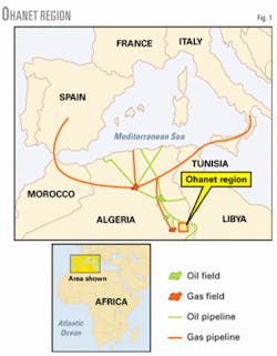
The BHP Billiton-Sonatrach gas processing plant, completed in 2003, is now online and producing sales gas, LPG, and a condensate product. The Ohanet plant is in the Illizi province of Algeria, about 1,300 km southeast of Algiers and 100 km west of the country’s border with Libya.
The Ohanet gas treatment plant consists of two parallel trains, each designed to treat 10 million cu m/day, or about 355 MMscfd. The plant treats reservoir gas, condensate, and free water from multiple wells via a transport-line network.
To meet the design basis requirement of a high degree of online availability, special features were included in the design to keep the plant online and operating reliably.
The facility is designed to process 20 million cu m/day (710 MMscfd) of well stream fluids from four reservoirs and as many as 47 wells (38 wells were available at start-up). The fluids are gathered in a system of branch flow lines and collection headers totaling 165 km of pipelines. The fluids feed a central processing plant designed to recover about 80% of the LPG components in the gas.
All of the products are exported via existing Algerian pipeline infrastructure. Three short export pipelines were built to tie in the facilities to the existing network. These include a 17.5 km, 28-in. gas line, a 17.5 km, 10-in. LPG line, and a 1.2 km, 8-in. condensate line.
The process units include:
• Primary separation.
• Front-end compression.
• Carbon dioxide removal.
• Gas dehydration.
• Gas expansion.
• LPG-condensate fractionation.
• Dry (sales) gas compression.
• Storage.
• Utilities.
Work in a remote location also required housing for operations personnel on rotation. The project therefore included a 150-man camp, workshops, warehousing, and an administration center including a fire station and medical facilities.
Design considerations
An important project requirement was a high operational uptime target, which had to recognize the remote location and reduced access to spares and technicians. We conducted availability modeling to help identify key design aspects of the process plant.
The study concluded that the single largest benefit was to consider having a third, 50% spare turbine-driven export compressor and remove routine maintenance work from the annual shutdowns. We considered aero-derivative compressors, but the review concluded that the cost and considerable local experience with heavy-frame machinery was a more effective solution.
In addition to availability modeling, we considered plant operability in the design. The designers accepted the fact that process trips will occur and focused on reducing the recovery time. Some key features of this design make this plant unique in Algeria.
Remote well control
The complex landscape and long distances between wells were also a problem for production operations; the farthest wells were more than 35 km from the plant with difficult terrain between.
To minimize time between well operations, 11 manifold stations were used with up to four deviated wells drilled from each, which reached the intended reservoir target below ground. Deviated wells allowed us to place the wellhead tree a few meters from the adjacent tree, but each wellbore would be kilometers from each other.
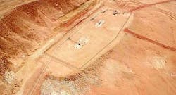
Fig. 2 shows the remote wellsite.
More than 30 of the 47 wells (the most remote wells) are controlled with fiber-optic cabling that links well control panels back to the central control room. This allows the panel operator the flexibility to manage flow without shutdown or outside assistance.
A well shutdown requires local intervention to reopen the well safely; this helps to avoid potential damage due to locked-in high pressure or high-erosion flows damaging well piping or wellbores. Similarly, the operator could ramp up the start-up flow remotely, which avoids the same potential dangers and allows the operator to feed fluids forward as they are received.
Heat exchangers
Process optimization showed that the heat-transfer surface upstream of the expander required either many conventional exchangers or a brazed-aluminum exchanger. The latter has been used in Algeria but the designers considered using fusion bonded, printed-circuit heat exchangers, which were deemed to be more rugged and would allow a relatively faster cooldown without damage.
Expander liquids pump
In traditional designs, the turboexpander outlet fluid directly feeds the de-ethanizer or demethanizer column. Poor experience during start-ups, shutdowns, and turndowns persuaded the designers to add an expander outlet drum and pump the fluid to the de-ethanizer.
This allayed the concerns of lube oil dilution at the expander and in two-phase flow and allowed the column to be pressure controlled independently from expander outlet. The latter allows the operator to maintain tight control of the column outlet temperature to achieve the necessary liquids specification.
Manageable isolation systems
The isolation philosophy required, as part of the safety system, separating the process plant into manageable systems. More manageable-sized systems meant that emergency shutdown valves could reduce the inventory available to potential leaks and also reduce the inventory of the potential system for isolation and maintenance during repair or inspection work.
Mole sieve regeneration heater
Achieving short-term high temperatures was a potential difficulty for the waste-heat-recovery system during winter. Separating the requirement of the short term, high-temperature demand of the regeneration system vs. the continuous lower temperatures in the process reboiler also led to greater operational stability during start-ups and allowed us to use a lower-grade heating medium.
Using separate direct-fired heaters removed the demand from the main waste-heat-recovery system and lessened the steadier demand for heat duty from the process, which helped avoid potential ripples during start-ups.
Operating envelope
Operational flexibility is required because four separate fields feed the plant and, subject to commercial and reservoir requirements, any combinations of flow are possible. The reservoir fluids were deposited in two geological periods, Devonian and Ordovician, the former being rich in liquids, the latter is fairly lean but rich in CO2.
During plant development, many profiles were generated and the designers realized that contrary to early considerations it was never likely that the plant would be filled entirely of rich or lean fluid. A balance between the two fluids allows the optimal requirements for process units, heat demand, and front-end compression.
Studies also showed that it was beneficial to split the inlet facilities into two slug catchers to receive Ordovician and Devonian fluids separately. This allows for an accelerated production profile for the rich Devonian reserves, which will ultimately require earlier front-end compression for the lower pressure due to faster depletion.
Keeping the high-CO2 Ordovician fluids separate allowed the designers to treat a smaller slipstream of the flow to achieve the final specification.
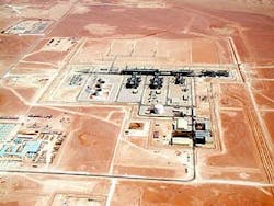
Fig. 3 shows the central process plant. The LPG spheres are on the left, with the condensate storage tanks just to the right of them. The main pipe rack runs east-west with the two process trains branching off of the main rack.
The small branch off the main rack to one side of the process trains is the amine system. Following along the main pipe rack from right to left are the inlet slug catchers, the inlet compressors, multinational contractor and craftsmen buildings, the three export-gas compressors, hot-oil storage, and the fired heater.
The facilities in the lower left are temporary housing, offices, and warehouse buildings used during construction.
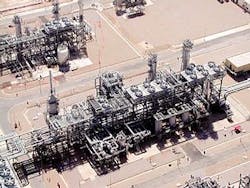
Fig. 4 shows one of two cryogenic trains in the plant. The de-ethanizer and depropanizer are in the upper right. The condensate stabilizer is in front of the pipe rack on the right. The direct-fired molecular sieve regeneration heater is on the left in the middle of the picture.
Plant products
The plant is designed to produce a dry export gas with less than 50 ppm of water, a dewpoint less than -6° C. at 81.5 bara, and less than 2% CO2 at the export battery limit. The plant produces a mixed LPG product of propane and butane; its target of at least 80% recovery of the components from the inlet gas streams is defined within an envelope of the peak liquids case and the peak gas case.
The LPG specification requires no more than 3 mole % ethane and no more than 0.4 mole % pentanes and heavier liquids. The condensate product must have an rvp of less than 0.5 bara (7 psia) in the summer and less than 0.69 bara (10 psia) in winter. The condensate product specification requires less than 0.5% bs&w.
Major equipment
The two fields requiring a pressure boost are compressed with two 10 Mw (12,700 hp) feed-gas compressors. These were projected for use within 2 years of start-up, subject to the demand for liquid recovery; however, richer-than-expected Ordovician gas may modify this schedule.
High-CO2 inlet gas is treated in a 180 cu m/hr (1,000 gpm) amine plant. Part of the gas bypasses the amine plant to control the amount of CO2 removed and to minimize the amine unit’s size and corresponding requirement for regeneration heat.
Gas is exported into the existing Algerian infrastructure by three 50%, 25 Mw (30,000 hp), heavy frame, gas-turbine driven recompressors. The recompression section consists of three 50%, two-stage centrifugal compressors.
Each train is equipped with a 7,500 kw (10,000 hp) turboexpander. The expander outlet in each train is routed to a vertical separator. Cryogenic pumps move the liquid from the expander outlet separator to the de-ethanizer. The separator and cryogenic pumps provide a uniform flow of liquid to the column and avoid the slug flow that is normal for plants in which the expander outlet goes directly to the de-ethanizer.
Because the expander outlet flows down into the separator rather than up into the column, cryogenic liquid has no chance to drop back into the expander and dilute the lube oil.
Four 500-cu m (150,000-gal) spheres provide LPG storage. One sphere is reserved for off-specification product. The LPG product is rerun in case the product is off specification.
The spheres have blanket gas to maintain pressure in the spheres at low ambient temperatures. The blanket gas must be used with care to avoid contaminating the product. Blanket gas is only used to maintain the pressure while the tank is being pumped out. Blanket gas is not used when product is being directed to the tank from the process or from the product pump minimum flow.
Two 6,000-cu m (42,500-bbl) tanks provide storage for the condensate product. The Algerian government requires that condensate is sold by strapping the storage tanks and does not allow metering for condensate sales. One 2,000-cu m (13,000-bbl) tank handles off-specification condensate product.
Infrastructure
Buildings in the plant include an administration building, vehicle maintenance building, a general maintenance building, a warehouse, a fire station, residence for the fireman, control building with offices, several multinational contractor and craftsmen buildings, an open-sided building for the export-gas compressors, and an open-sided building for the feed-gas compressors. An offsite camp was included in the project to house 150 operational and maintenance people.
Plant construction
The construction of the Ohanet plant involved the movement of nearly 36,000 tonnes of equipment and supplies to the site, including the largest single heavy vessel in Algeria at the time. Management of more than 3,000 multinational contractors and craftsmen in the Sahara desert required extensive planning to get the job done in only 37 months.
Health, safety, and environmental efforts were extensive; but they were justified by the small number of lost time injuries.
Plant commissioning
The plant was commissioned in fall 2003. Once the plant was checked out and ready for start-up, it was pressure tested with nitrogen at normal operating levels.
High-pressure leak testing prevented the lengthy shutdowns required to inert, repair, and return the plant to operation and was considered as essential to test the “unknown” quality control of local contractor personnel.
The plant started up fairly well for a grassroots facility of this size and complexity. Two pump systems failed during early operations (magnetic drive, hot-oil pumps and cold vertical can pumps), which were replaced by pumps of a different design.
Performance tests were conducted and the plant was tested in accordance to the test plan. Results and performance since testing in 2004 are positive-the plant has achieved its availability targets and exceeded expected LPG recovery criteria.
The project scope included extended support through the provision of a warranty engineer. The warranty engineer was expected to complete his assignment in June 2005.
The authors
Bruce D Brown ([email protected]) is a principal in the technology development and process engineering department at ABB Lummus Global, Houston. He has also served as manager of process technical services at ABB. Brown holds a BS in chemical engineering from Montana State University. He is a member of GPSA.
Andreas Pelekanou ([email protected]) is an engineering manager for Amerada Hess Corp., London. He served as engineering manager for the Ohanet Project when he was at BHP Billiton. Pelekanou holds a degree (1978) in chemical engineering from Imperial College, London. He is a member of the Institution of Chemical Engineers.
Yogesh Joshi ([email protected]) is process manger-upstream at ABB Lummus Global BV, The Hague, Netherlands. He was the lead process engineer for the Ohanet Project for ABB Lummus Global. Previously, Joshi was a senior process engineer at Kinetics Technology International BV. Joshi holds a Bachelor of Technology, Chemical, (1984) from the Indian Institute of Technology, New Delhi.
Robert Page was the lead process engineer for Petrofac International Ltd., Sharjah, Dubai, on the Ohanet Project. His responsiblities included pipelines, inlet slug catchers, and the amine plant.


