Field troubleshooting improves steam surface-condenser performance
Karthik Rajasekaran
Shell Oil Products US
Norco, La.
Norman P. Lieberman
Process Improvement Engineering
Metairie, La.
Declining performance of a large compressor-driven steam turbine's surface condenser at Shell Chemical LP's petrochemical complex in Norco, La., was constraining an associated process unit to a maximum 80% of its design capacity, significantly affecting the unit's operating margin and energy efficiency.
Working with the surface condenser's original manufacturer to troubleshoot the issue, the authors executed several online field tests that revealed a critical component of the steam-jet ejector system—the combined intercondenser-aftercondenser (IC-AC)—had developed an internal division-plate leak. To remedy the malfunction, the permanent steam-jet ejector system was modified so that the second-stage ejectors were routed directly to the atmosphere, eliminating performance losses associated with the leak.
With the unit still not performing to the operator's desired level, however, the authors conducted further field tests and discovered restriction of the IC loop seal. Based on the authors' recommendation, the loop seal was cleaned during a planned unit turnaround. The cleaning resulted in improved condenser performance, increasing both operating margin and efficiency of the associated process unit.
This article discusses the unit system and equipment, system deficiencies discovered during the field investigation, and recommendations undertaken to address those deficiencies.
Equipment overview
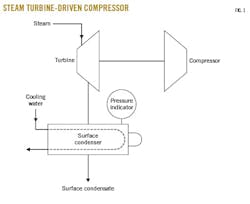
The surface condenser at Norco is part of a compressor-driven steam turbine critical to an associated process unit at the plant. Equipped with a two-stage steam ejector, the condenser consists of a fixed-tube heat exchanger that uses cooling water to condense turbine-exhaust steam which flows back into the condenser. Because it's desirable to condense steam at the lowest-achievable pressure to maximize work developed by or energy extracted from each pound, surface condensers are designed to operate at the highest quality vacuum possible. The effects of improved surface-condenser vacuum can be approximated as an isentropic expansion on a Mollier diagram, or enthalpy–entropy chart, which plots the functional relationship between enthalpy, entropy, temperature, pressure, and steam quality.
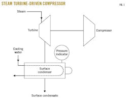
Fig. 1 shows a diagram of the compressor-driven steam turbine. Fig. 2 shows a detailed diagram of the surface condenser.
The vacuum generated in a surface condenser by the condensation of steam cannot be maintained without a continuous, noncondensable gas-removal device to remove air and other noncondensable gas from turbine-seal leaks. It's also possible for minor noncondensable contaminants in the steam, like carbon dioxide, to enter the surface condenser.
This surface condenser uses steam ejectors for noncondensable removal, connected directly to the sides of the surface condenser (Fig 2). The condenser includes an air-cooling section, where up to 30% of the available heat-transfer area is devoted solely to minimizing the load on the steam ejectors. Condensing as much water vapor as possible from the stream entering the steam ejectors is important because water vapor increases loading on the ejectors.
The ejectors themselves work by expanding motive steam through a specially designed nozzle (similar to those on the exhaust of rocket engines) designed to maximize the steam's exit velocity. This isentropic expansion results in a local low-pressure area generated around the nozzle into which gases from the surface condenser naturally flow because of pressure differential (from high to low pressure).
In a properly working ejector, the motive steam accelerates these gases from the surface condenser to supersonic velocities so that the combined gases enter the converging part of the ejector diffuser. In this converging section, supersonic gases increase in pressure as the cross-sectional area drops. As the converging section ends, the supersonic gases slow to the speed of sound in the throat section where a sudden sonic shock occurs as the gases transition to subsonic velocities. Then, in the diverging section of the ejector, the cross-sectional area increases, enabling pressure of subsonic gases to increase as they leave the ejector. This is how the ejector functions as a vapor compressor.
If the ejector isn't working properly, however, and gases aren't traveling at design velocities across the different areas of the ejector, ejector performance declines substantially.
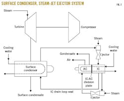
Vapors from the condenser's first-stage ejector are routed to an IC designed to condense as much water vapor from the gases as possible. This serves to unload the second-stage ejectors, while condensed water is returned to the surface condenser. Because the IC operates at a higher pressure than the surface condenser, condensed liquid must pass through a loop seal before returning to the surface condenser to prevent vapors from simply blowing through and recycling around to the first-stage ejector's inlet.
The IC also includes its own air-cooling section to help minimize the water-vapor content of the stream entering the smaller second-stage ejectors.
Second-stage ejectors work on the same principle as first-stage ejectors with the exception that they discharge into an AC operating slightly above atmospheric pressure. This enables any gases in the AC enough pressure to flow freely into the atmosphere without requiring further compression. Condensate generated in the AC typically drains back into the surface condenser as well, except that instead of a loop seal, a steam trap prevents vapor blowby into the surface condenser.
While this installation uses two stages of ejectors, more stages are possible depending on process requirements. Also unique to this installation is the combined IC-AC, which is a single exchanger separated by an internal division plate (Fig. 2). In the Norco plant, condensate generated in the AC is routed to an open drain rather than being routed back to the surface condenser. The AC's remaining noncondensable gases are simply vented to atmosphere.
Field investigations, step solutions
Operating data showed the surface condenser was performing poorly relative to its design, and performance was gradually worsening. Since the associated turbine was running at its maximum steam flow, the surface condenser's declining performance was limiting the amount of work achievable by each pound of steam entering, making the turbine unable to deliver its maximum power output and restricting overall unit performance. Specifically, the second-stage ejectors were operating above their designed suction pressure.
Field measurements executed with the original equipment manufacturer eliminated typical causes for poor ejector performance, including high noncondensable inleakage, poor motive quality, and poor cooling-water supply. The initial theory was that both second-stage ejectors were in some way damaged, so replacement ejectors were ordered. Following installation of the new ejectors, however, operating data showed a negligible improvement in performance, indicating the mechanical condition of the second-stage ejectors was not the main cause of the poorly performing equipment.
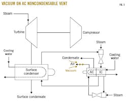
Further field data collected ultimately confirmed the presence of a slight vacuum on the AC's noncondensable vent, which should have been impossible since the AC was designed to operate at slightly above atmospheric pressure (Fig. 3). Subsequent field testing revealed the vacuum was occurring because of a leak in the IC-AC division plate (Fig. 2). This division-plate leak allowed gases to flow from the AC back into the IC, effectively recycling flow across the second-stage ejectors. The recycled flow, in turn, severely impacted the ejectors' ability to maintain designed suction pressure because of vapor loading on the ejectors at rates well above design.
This division-plate leak was resolved online by venting the second-stage ejectors to the atmosphere. Following this modification to the IC-AC, the division-plate leak no longer affected performance of the vacuum system or surface condenser, and second-stage ejector suction pressures returned to designed operating values.
Despite large improvements in the surface condenser's performance, the condenser still was operating well below design performance. The integrity of the IC drain-loop seal came into question after additional field testing revealed the presence of a high pressure drop between first-stage ejector discharge and second-stage ejector suction.
Flushing fix
To address the issue, the authors recommended flushing the loop seal during a turnaround. Once under way, initial turnaround inspections showed that the surface condenser's tubes were quite clean. Flushing of the loop seal, however, revealed a large quantity of muds and solids at the seal's bottom. No other major works were completed on the condenser as part of the turnaround.
Upon restarting the unit following the maintenance, the operator noted a major improvement in the surface condenser's performance, lending credence to the theory that the loop seal was responsible for the condenser's previous poor performance.
Before cleaning, the restricted loop seal was causing water to back into the IC. This high-water level, combined with a vertical baffle design that forced the second-stage ejector suction gases through a tortuous path, resulted in a very high pressure drop.
Following the turnaround flushing, the surface condenser's performance improved to its highest levels in more than 10 years. Now operating at nearer to designed rates, the condenser enabled the attached turbine to improve its workload by more than 10%, resulting in increased throughput for the associated process unit at no cost.
Additional considerations
Although surface-condenser performance following the loop-seal flushing exceeded original expectations, the condenser still did not perform precisely according to its design, which could be explained by the following:
• Most of the gap between design and actual performance can only be attributed to a problem within the surface condenser. The exact nature of the problem cannot be determined, as it's a fixed-tube sheet exchanger. While this makes it impossible to inspect properly, the result is the same. Regardless of whether caused by leaking air baffles or shell-side fouling (possibly due to silicates or salts), the exchanger must be dismantled to be replaced or redesigned.
• The calculated cooling-water flow to the surface condenser is only 75-80% of design cooling-water flow to the unit, indicating hydraulic issues with the plant's cooling-water network. While seemingly a large disparity, it's only responsible for a small part of the performance gap.
• This surface condenser was designed for only about two thirds of the steam flow currently passing through it. Again, though seemingly a large disparity, it's responsible for only a small part of the performance gap. This flaw can only be resolved by redesigning the exchanger.
Broader application
This troubleshooting exercise led to some key insights into the operation and design of surface condensers: specifically, the actual effects of the performance of noncondensable removal units on the heat transfer properties of condensing heat exchangers (in this case, steam).
An earlier theory as to how a noncondensable gas like air affects the effective heat-transfer coefficient of condensing steam proposes that, while the air concentration in a steam-surface condenser may be very low relative to the overall concentration of steam, the air concentration around the cooling-water tubes is much higher than that in the entire surface condenser.1 Even though steam contacts the tube and water formed via condensation can simply fall via gravity, air that is present in the surface condenser cannot escape except by backwards diffusion against the vapor stream approaching the tube.
The velocity of the steam around the tubes has a large effect on the effective heat-transfer coefficient. If the steam's velocity becomes too low then the air concentration around the surface increases to an extent that reduces the effective heat-transfer coefficient.
A separate earlier theory proposes that noncondensable gas (air) builds up at the interface where condensation occurs, lowering the partial pressure of the overall vapor, and in turn, lowering the interface temperature at which condensation occurs as well as reducing the heat-transfer rate via reduction of the thermal driving force.2 The theory further notes a dramatic difference in the extent of heat-transfer reductions brought about in the presence of noncondensable gas, especially in the gravity flow-condensation configurations upon which most surface condensers are designed.
Results of the performance investigation presented in this article may substantiate these theories in a practical application. Lowering the first-stage ejector's discharge pressure by improving performance of the second-stage ejectors and reducing the pressure drop across the IC resulted both in a large unloading of the first-stage ejector and an enabling of higher vapor flow from the surface condenser into the first-stage ejector suction chamber. This higher vapor flow increased the gas velocity across the cooling water tubes, especially in the air cooling sections of the surface condenser, which can be up to 30% of the total heat-transfer area. This improved velocity and flow to the first-stage ejector accomplished what existing theories had predicted: that a higher gas velocity across the tubes would reduce the local concentration of noncondensables around the tubes via improved diffusion. This reduction in local noncondensable concentration, then, would increase the effective heat-transfer coefficient considerably.
References
1. Silver, R.S., "An Approach to a General Theory of Surface Condensers," Proceedings of the Institution of Mechanical Engineers, Vol. 178, Part 1, No. 14, 1963-64, pp. 339–376.
2. Sparrow, E.M., Minkowycz, W.J., and Saddy, M., "Forced Convection Condensation in the Presence of Noncondensables and Interfacial Resistance," International Journal of Heat and Mass Transfer, Vol. 10, No. 12, December 1967, pp. 1829-1845.
The authors
Karthik Rajasekaran ([email protected]) is a process engineering team lead for Shell Oil Products US in the olefins production area at Shell Chemical LP's manufacturing complex in Norco, La. In his 10 years with Shell, Rajasekaran has held various roles in process engineering support, including environmental, utilities, ethylene steam cracking, and fluid catalytic cracking. He holds a BS (2007) in chemical and biomolecular engineering from Tulane University in New Orleans.

Norman P. Lieberman ([email protected]) is a chemical engineer with more than 50-years' experience in process plant operation, design, and field troubleshooting. He previously served as operations supervisor, technical service manager, and plant manager at US refineries until 1985. An independent consultant, he also has taught 800 seminars on troubleshooting refinery process problems to 19,000 engineers and operators. An author of nine textbooks on plant process problems and operations, he holds a BS (1964) from Cooper Union for the Advancement of Science and Art and an MS (1965) from Purdue University, both in chemical engineering.
