EG injection, gas plant relocation-expansion highlight offshore storage plans
Studies to expand underground natural gas storage offshore northern Spain determined the technical and economic feasibility of ethylene glycol (EG) injection to prevent hydrate formation and the relocation ashore of gas treating from the existing manned production platform offshore.
To serve the rapidly growing natural gas market in Spain and meet the swing capacity required by peak winter demand, joint-venture partners Repsol-YPF and Murphy Spain Oil Co. planned the expansion of their existing offshore underground storage. Target production volume is 20.6 million normal cu m/day (MMcmd; about 727 MMscfd) at a maximum wellhead pressure of 280 kg/sq cm (about 4,000 psi).
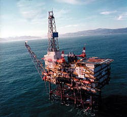
The natural gas storage is in the Gaviota offshore reservoir, and the gas treatment and compression facilities are ashore, connected by subsea pipeline to the Gaviota platform.
Repsol-YPF, with assistance from Bechtel Corp., IPSI LLC, and Diseños y Proyectos Reunidos SA (Diseprosa), Madrid, conducted the feasibility study and basic design to establish the viability of expanding the existing underground storage, to choose facilities options, to estimate life-cycle cost and economics, and to plan the expansion project implementation.
The assignment afforded opportunities for innovative solutions to gas treating and pipeline transportation.
The process studies concluded that neither methanol injection nor the more traditional heating of feed gas at the inlet of the onshore gas treatment plant accompanied by triethylene glycol gas dehydration would be technically and economically preferred for this expansion project.
The study found the superior solution to be injection of EG with use of a reclaimer to remove potential salt contamination from EG. Moreover, the existing offshore platform will have its life extended by 20 years and be recertified as an unmanned wellhead platform.
As stated, the offshore processing facilities will be decommissioned because all gas treating will be onshore. Six additional wells will be drilled to accommodate the expanded gas injection and withdrawal rates.
As the offshore platform will have minimum facilities, the bi-directional gas injection-production sealine between the treatment plant ashore and the Gaviota platform offshore will be designed for multiphase production with inlet pressures, at both ends, ranging from 90 to 280 kg/sq cm.
Pipeline transient analysis identified the operating conditions that influence selection of the optimum pipe OD for the multiphase production cycle. Methods to install the offshore pipeline on a mostly rocky sea-bottom were also established.
The area available to expand the gas treating and compression plants is constrained within a very limited and steeply graded plot by the existing property line. This challenge was met by use of skid-mounted packaged units and employing offshore platform layout approaches.
Existing facilities
To serve rapidly expanding demand for natural gas in Spain, Repsol-YPF and Murphy Oil plan a threefold increase of the working-gas capacity of the Gaviota reservoir, from 780 to 2,225 MMcmd, and to increase the peak gas injection and withdrawal rates to 13.7 MMcmd and 20.6 MMcmd, respectively, with minimum injection and withdrawal rates of 1.0 MMcmd.
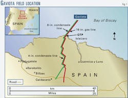
The Gaviota reservoir, in the Bay of Biscay, east of Bilbao, Vizcaya, Spain, is 2,200 m below sea level and was in primary production from 1986 to 1993 (Fig. 1). The reservoir originally produced natural gas and 55.8° API condensate. The offshore production and onshore processing facilities were designed for gas peak production of 5 MMcmd.
When it was converted to gas storage in 1994, the Gaviota reservoir was only the second offshore natural gas storage field in the world. At present, natural gas is injected for storage from March through September at an average of 3.6 MMcmd and withdrawn from October through February at an average rate of 5.2 MMcmd. Injection gas is metered and compressed onshore and pipelined to compressors on the platform for final compression to injection pressure.
During gas withdrawal, hydrocarbon and water produced from storage are separated on the Gaviota platform, and wet gas and condensate are transported ashore to the plant through the 16-in. sealine with a design pressure of 110 kg/sq cm.
The produced wet gas is dehydrated onshore and delivered to the gas grid after metering and odorization. Methanol is injected on the platform for hydrate prevention and water removal. Onshore, ammonia refrigeration is used for hydrocarbon dew-point control. The condensate is stabilized and loaded into tank trucks.
As the future plan requires more than tripling the gas injection and withdrawal rates, a feasibility study was conducted to select the technically and economically preferred options for the onshore gas treatment plant (GTP), the injection facilities, and the onshore and offshore pipelines.
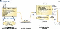
It was established early in the study that the preferred solution was to operate the pipeline at wellhead pressures and convert the existing platform to an unmanned wellhead facility by relocating all gas processing and compression facilities to an expanded onshore gas treatment and compression plant (Fig. 2).
Gas treatment
The composition of the produced gas is such that hydrates can form at temperatures lower than 17° C. The seawater temperature and the large pressure reduction necessary at the inlet of the onshore GTP during withdrawal make hydrate prevention necessary for the sealine and the GTP.
The method selected must be effective during steady state, transient, and shut-in conditions. Three common methods to prevent hydrate formation are:
- Inhibitor injection; typically methanol and glycol.
- Heating of the feed gas to greater than the hydrate-formation temperature.
- Removal of free water by dehydration.
Inhibitors prevent hydrates by providing a sufficient concentration of material soluble in the aqueous phase that competes for the water molecules or ions. This prevents the water from forming solid hydrates with the hydrate forming constituents in the gas or non-aqueous liquid phase.
Following is a description of the hydrate prevention options studied:
- Option A, inject methanol (MeOH). In this option, MeOH is injected on the platform to control potential hydrate formation due to cooling in the sealine. In addition, because of the cooling caused by the Joule-Thomson (JT) effect at the GTP inlet-control valves, methanol is injected upstream of the pressure-control valves and upstream of the hydrocarbon dew point-control refrigeration system.
- Option B, preheat feed and inject methanol. MeOH is injected on the platform, as in Option A, to control hydrate formation in the subsea pipeline. The feed stream is heated upstream of the pressure-control valves at the GTP inlet and MeOH is injected before hydrocarbon dew point control.
- Option C, preheat feed and TEG dehydration. Achieve hydrate prevention in the sealine by injecting MeOH. Prevent hydrate formation due to temperature drop induced by JT effect at the GTP inlet-control valves by heating the feed gas at the GTP's inlet. Remove entrained water in gas by TEG injection.
- Option D, inject EG. Achieve hydrate prevention in the sealine by injecting EG. Prevent hydrate formation due to JT-valve pressure reduction and remove entrained water in the gas upstream of the hydrocarbon dew point control system by injecting EG. Saline formation water may degrade the EG.
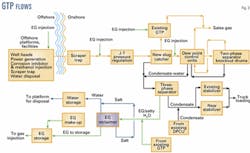
- Option E, inject EG plus regeneration of EG. The hydrate-control method is the same as Option D. Additionally, a proprietary process regenerates EG by removing dissolved salts. Fig. 3 shows this GTP process option.
Technical and economic comparisons showed that Option D has the lowest capital cost, the lowest operating cost, the lowest consumption of chemicals, and the smallest plot space requirement. This is the preferred option for low-salinity formation water.
The produced formation water may have high salinity, however, and because gas-water separation is infeasible at the high end of the range of pipeline operating pressures considered, there is no opportunity to remove formation water before pressure reduction at the plant's inlet, and the EG will mix with the produced formation water and its associated salts.
Conventional regeneration of glycol involves heating the glycol solution to drive off water and concentrate the glycol for reuse. The high temperatures required can cause thermal degradation of the glycol, which can reduce inhibition effectiveness and increase cost. Furthermore, salts tend to remain in the glycol as water is removed, eventually increasing salt concentration to unmanageable levels.
A proprietary process, previously used in chemical plants, is available to separate salt from glycol. The process, based on vacuum distillation and including heating techniques to reduce equipment fouling, can be designed for a partial slipstream or the full glycol flowrate. Regenerated glycol purity in excess of 98%, and glycol-recovery factors up to 99% are achievable.
Hydrocarbon dew point control
The hydrocarbon dew point specification is -2° C. at all pressures and the simulation indicates that the gas needs to cool down to -22° C. in order to meet the specified hydrocarbon dew point.
The mechanical refrigeration process options include ammonia, propane, and freon refrigeration. Ammonia refrigeration was selected for the hydrocarbon dew point control for several reasons:
- Ammonia is widely available.
- The refrigeration level at -22° C. is suitable for ammonia refrigeration.
- Any leak is not critical and will be easily detected. Ammonia is not as flammable as propane.
- The heat-transfer coefficient is higher for ammonia, requiring more compact heat exchangers.
- Ammonia refrigeration is more environmentally acceptable than propane or freon refrigeration.
Three-phase separators and an absorber tower were selected to stabilize the condensate. The stabilizer-tower process is recommended over the flash-separator process because of increased condensate recovery. In general, higher flowrates favor the stabilizer-tower process. For environmental reasons, the stabilizer overhead vapor and the three-phase separator vapor will be reinjected back to the feed gas.
The unstabilized condensate that is collected in the slug catcher and in the condensate knockout drum will be depressurized to the existing and a new condensate stabilizer unit. These units will flash off, in trayed columns, the lighter components to the fuel gas system or to an overhead compressor for recovery into the gas plant's feed stream.
The total flow of stabilized condensate will be transferred to an existing floating-roof storage tank and then moved 30 km by pipeline to a remote truck-loading station.
The recovery of the EG hydrate inhibitor depends heavily on the separation efficiency of the three-phase separators. Any deficiency in the separation causes EG to be lost to the condensate.
The JT-valve effect at the GTP inlet will cause emulsification of the EG in the condensate. This makes the separation between the EG and condensate more difficult.
Therefore, the study recommended three three-phase separators with 20 min residence time to obtain high efficiency on the EG, water, and condensate separation. These three-phase separators also function as the first-stage flash drum for condensate stabilization process.
There are gas-gas and gas-liquids heat exchangers upstream of the refrigeration unit in order to minimize the horsepower of the refrigeration unit. Similarly, there are liquids-liquids exchangers upstream of the condensate stabilizer and EG reclaimer to minimize the heat duty for the condensate stabilizer and EG reclaimer.
Compressor station
Initial evaluations showed that the preferred compressors for this application are centrifugal compressors with gas seals, skid-mounted, and driven, either directly or through a gearbox, from their respective gas-turbine drivers.
Evaluation of the compression options included a comparative analysis for the compressor configuration options:
- Option A: Three turbines driving six compressors plus one spare turbine driving two compressors.
- Option B: Four turbines driving eight compressors plus one spare turbine driving two compressors.
- Option C: Two new turbines driving four compressors; relocate three Solar Taurus; reuse two existing onshore Solar Taurus plus one spare turbine high-pressure compressor.
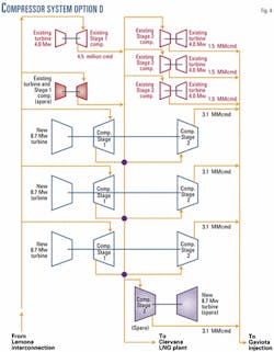
- Option D: Three new turbines driving six compressors; relocate and reuse three Solar Taurus from the platform; reuse two existing onshore Solar Taurus plus a spare turbine HP compressor.
- Option E: One new low pressure and two new high-pressure turbocompressors; relocate and reuse three Solar Taurus from the platform; reuse two existing onshore Solar Taurus plus one spare turbine LP compressor and one spare turbine HP compressor.
Option D was preferred for the following reasons:
- The turbine compressor, auxiliaries, and piping will fit into the existing 22 m x 60 m compressor area.
- The compressors have sufficient operating flexibility to handle injection flow rates between 1 and 13.7 MMcmd at outlet pressures of 90 to 280 kg/sq cm. Options C, D, and E, which utilize existing small turbines-compressors, will be able to handle the proposed operating conditions with minimal recycle.
The larger compressors in Option A and B are less flexible to handle low flow rates and would require recycle at flow rates less than 3 to 4 MMcmd.
- Options C, D, and E utilize the existing equipment helping in standardization and contingent benefits.
- Options C, D, and E have the flexibility to operate at low flow injection rates with minimum recycle.
Fig. 4 shows the recommended Option D.
Pipeline systems
The pipeline components in the project are as follows:
- Onshore pipelines between GTP and the national grid. A new 24 in., 30-km pipeline will supply gas from the national grid to the GTP. The same pipeline will be used to return the treated withdrawal gas to the gas grid. The increased gas volume is to be shared between the new line and the existing 16-in. pipeline.
- Onshore condensate pipeline. An existing 4 in., 30-km pipeline will run from the GTP to Erleches where the condensate will be loaded into tank- trucks.
- Existing offshore pipelines between Gaviota platform and the GTP. Currently there are two offshore pipelines, one 16-in. OD and the other 6-in. OD. The 16-in. line is used for injection and production at a design pressure of 110 kg/sq cm. The 6-in. line is used to transport methanol to the platform for injection for hydrate control. In the expansion project, these two pipelines are slated for different services.
- New offshore pipeline between Gaviota platform and the GTP. This sealine will be used for both production and injection cycles.
During the production cycle, the fluid in this pipeline will consist of wet gas, condensate, and free water. During injection, the same pipeline will transport gas at injection pressure from the onshore compressor plant for injection into the reservoir.
As the production mode is the governing design condition, the new sealine will be designed for multiphase flows and operating pressures ranging from 90 to 280 kg/sq cm.
The design of the new sealine between the Gaviota platform and GTP offered significant challenges. For multiphase gas flow, the optimum pipeline design is generally associated with the smallest diameter which accommodates the desired design flow rate at the given pipeline inlet and outlet pressures, while maintaining sufficiently high gas-liquid phase velocities to minimize liquid holdup and slugging within the line.
Optimizing the pipeline diameter can provide the following benefits:
- Minimizes liquid holdup and slug sizes by providing higher gas-liquid velocities.
- Provides better flow rate turndown capacity without flow regime change or increased slugging.
- Provides more stable operation.
- Minimizes capital cost.
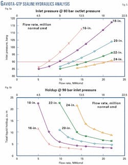
The initial steady-state analysis to establish the range of pipe sizes was performed with Pipesim and Olga software. The pipeline outlet pressure was maintained at 80 kg/sq cm and five pipe sizes, 16 in. through 24 in., were analyzed. Fig. 5 summarizes the results of this analysis.
The results of the liquid hold-up analysis for the 24-in. pipeline showed high liquid hold-up at low flowrates (2.7 MMcmd and lower), which could lead to liquid buildup in the pipeline or severe slugging. The 16-in. pipeline has good turndown but required high inlet pressure for design flow rates.
Consequently, the 16 and 24-in. pipelines were not evaluated further.
Transient analysis for 18, 20, and 22-in. pipe diameters was carried out with Olga 2000 software for the following scenarios: transient flow rate analysis; ramp up cases; and operation within the two-phase envelope.
Following are the results of the multiphase pipeline analysis:
- The 22-in. pipeline is more susceptible to higher liquid holdup and potential slugging due to lower gas-liquid velocities.
- The 18 and 20-in. pipelines gives the best results with regard to lower liquid holdup, flowrate rangeability, and slug sizes.
- Operation of the pipeline at high pressure, within the two-phase region of the phase envelope, will have a higher minimum flow rate than operation at lower pressure.
- The 18-in. pipeline needs an inlet pressure of 115 bar at the design flowrate of 20.6 MMcmd, while the 20-in. pipeline requires 105 bar.
- The 20-in. pipeline will require bigger onshore slug catcher than the 18-in. pipeline.
- The recommendation, based on overall gas flow capacity, reasonable liquid holdup, and flow rate rangeability is for a 20-in. pipeline.
Construction
Several methods to construct the shore crossing were studied, including conventional trenching and horizontal directional drilling (HDD).
Preliminary assessments looked at HDD crossing lengths of 600 m and 1,100 m, extending 350 m offshore to about 10 m water depth. On the onshore side, drilling will commence 250 m from the landfall point, depending on a suitable site to install the HDD rig and equipment.
Conventional trenching with burial is also feasible and was in fact used for the existing pipelines. For installation of the crossing by conventional trenching, it is proposed to trench and to backfill with in situ material topped by a layer of stone and gravel. Sheet piling will be required for trenching in shallow offshore areas of water depth less than 5 m. The offshore pipelines will be laid conventionally by laybarge.
A comparison of the two options showed that the cost and time of installation by the conventional method are comparable to that for a 600-m HDD crossing.
Site constraints
The expansion project has several site constraints.
All new equipment installation and all modifications must be done within the existing plant boundary without interrupting ongoing operations. And, the space for the existing site was created by cutting into a hillside, in hard basaltic rock, but no blasting is allowed. Finally, existing compressors and process equipment are to be used as much as possible.
These constraints were overcome by, among other methods, minimizing cut and fills by keeping the existing contours as far as possible. And, the new gas plant process equipment was laid out on the existing helicopter landing pad and adjacent laydown area.
The constraints were also addressed by use of offshore platform techniques such use of skid mounted, packaged, or modularized equipment
Also, the new compressors are to be installed within the footprint of the existing compressor house. The compressor interstage coolers are on top of the turbine compressor packages to save plot space.
The constraints were also overcome by a new larger capacity slug catcher with a more space-efficient design located within the footprint of the existing slug catcher.
And finally, the layout and implementation schedule of the new facilities will permit construction simultaneously with continued plant operation.
Implementation plan, schedule
The schedule is based on injection plant start-up in April 2005 and production facilities start-up in October 2005. The schedule critical path is through the following activities:
- Finalization of design basis including reservoir studies.
- Oceanographic and geotechnical surveys.
- Project approval.
- Frontend engineering and design.
- Long-lead procurement.
- Permitting and land acquisition.
- Injection facilities.
- Production Facilities.
- New wells, drilling and completion.
Six new wells will be drilled with the drilling rig currently on the platform. The first two new wells will be completed before the start of the injection cycle in 2005. Once the existing high-pressure compressors are removed from the platform, it is expected that well drilling can be performed year round.
Hence, it is expected that two to three wells/year may then be completed.
The authors
Isidro Solórzano H. is a project development manager with Repsol-YPF, specializing in oil and gas field development. He holds a BS in mechanical engineering from Universidad de Cantabria, a BS in mining engineering from Universidad Politecnica de Madrid, and MBA in finance from Instituto Directivos de Empresa de Bilbao, all in Spain.
Ramon Torra is senior production technologist at Repsol-YPF with more than 30 years in process design in the oil and gas industry. He obtained his degree in chemical engineering from Barcelona University, Spain.
Roberto Reichard is a project manager and principal petroleum engineer with Bechtel Corp., specializing in oilfield development, production facilities, and pipelines. He holds an MS in petroleum engineering from Imperial College, London, and an MBA in finance from the University of Dayton.
Som Konar is a project manager with Bechtel Corp., San Francisco, and has 32 years in engineering and construction of offshore and onshore oilfield facilities and pipelines. He holds an MS in petroleum engineering from the University of Tulsa.
Vicente Arias Fouz is general manager of Diseños y Proyectos Reunidos SA, Madrid. He has 30 years in engineering and construction of chemical and petrochemical plants, oilfield facilities, and pipelines. He holds a PhD in industrial engineering from Escuela Técnica Superior de Ingenieros Industriales, Madrid.
J. C. Kuo is technology manager for IPSI LLC, Houston, an affiliate of Bechtel Corp. He has more than 25 years in gas processing, gas treating, and LNG. Kuo holds a BS from Chung Yuan Christian University, Taiwan, and an MS from the University of Houston, all in chemical engineering. He also holds an MS in environmental engineering from Southern Illinois University, Carbondale.

