Integrated workflow optimizes offshore designs
Offshore platforms must ensure long-term safety, stability, and operational efficiency under extreme conditions including hurricanes, waves, strong currents, and corrosion. Platform planning must integrate mooring systems, risers, and pipelines. Traditionally, these components have been designed separately, but recent advancements recognize that these components form an integrated system which jointly responds to environmental forces.
To address these coupled interactions, a novel integrated workflow combines these components to optimize platform placement, riser-base placement, riser design, and pipeline routing. It honors clearances and prohibited area constraints. The methodology includes a bathymetry map, wellhead or manifold locations, and design parameters as input. It optimizes riser locations within accessible corridors and efficiently lays out pipeline routes.
The workflow was tested on two cases: one case with three manifolds downstream to the platform and a more complex case with eight manifolds. Results show that the workflow correctly designed risers and efficiently routed pipelines and reduced the likelihood of infeasible or costly configurations.
Floating production system design
Traditional floating production system workflows treat risers, moorings, and pipelines as independent subsystems, designed sequentially and using specialized analysis tools that rarely communicate with one another. While effective for conventional shallow-water operations, these independent workflows introduce inefficiencies and risks when applied to deeper waters and more complex subsea architectures.
A report by SLB and American University of Beirut proposed a semi‑automated workflow that unifies platform design. It outlines mooring‑prohibited areas, locates riser bases, routes pipelines, and designs riser geometries in an integrated process. The process does not, however, attempt to fully couple hydrodynamic or structural physics. Instead, it coordinates all major layout‑level decisions to ensure feasibility, efficiency, and spatial consistency across the entire subsea development.
Historically, engineers design risers and mooring lines separately using uncoupled analysis which ignores nonlinear interactions between platform motion, riser dynamics, and mooring line behavior. Tools such as the non-linear integrated coupled dynamic analysis of floaters (NICDAF) have shown that risers and moorings exert substantial mass, inertia, and damping effects on the hull, especially in deepwater where lengths and weights increase dramatically. Neglecting these effects could lead to erroneous prediction of motions.
High deepwater hydrostatic pressures may require seabed or riser boosting to maintain production rates, while cooler seabed temperatures threaten flow assurance. Extreme metocean conditions induce fatigue in mooring and riser systems, and seabed bathymetry complicates the design process with escarpments and geohazards. An integrated workflow solves these issues better than isolated analyses.
Fully coupled programs, therefore, improve prediction accuracy but at the cost of computational demand. Practical engineering workflows still retain manual steps for selecting mooring specifications and riser placement. For example, mooring design remains heavily dependent on manual approaches for selecting azimuth angle, pretension, diameter, fairlead slope, and mooring radius.
Equally important to mooring and riser design are well placement, well-trajectory design, facility node placement, and pipeline routing. The latter has traditionally been treated as a separate discipline, yet routing strongly affects the placement of riser bases, the design of manifold networks, and the feasible arrangement of production infrastructure.
Pipeline routes must avoid steep slopes, geohazards, mooring zones, and other obstacles, while maintaining flow assurance and operational reliability. Small inefficiencies create major financial consequences due to the length and cost of subsea pipe and installation.
To improve route selection, researchers have explored geographic information systems, decision‑support tools, and fuzzy‑logic reasoning models, but most field developments still rely heavily on heuristic decisions.
Integrated workflow
The proposed integrated method does not attempt to solve the full field-development problem, which would require simultaneous optimization of wells, pipelines, risers, moorings, and facilities. Instead, it focuses on the spatial interplay among the platform, riser bases, and pipeline network. Wells and manifolds are assumed to have already been placed, though the workflow can be selectively coupled to earlier steps by feeding platform‑prohibited areas back into the optimization stage.
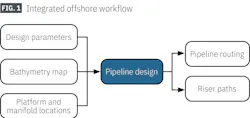
The design process begins once platform location, design parameters, and bathymetry are known (Fig. 1). The bathymetry map provides seabed elevation data for pipeline routing and riser-touchdown calculations, and it defines the spatial context to place all equipment.
Bathymetry-grid cells falling within prohibited regions are removed from the routing map. The map resolution determines the granularity of the routing grid. High resolution improves navigability around obstacles, particularly in tight spaces such as platform corridors, but it significantly increases computational cost.
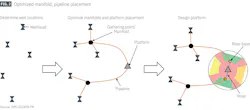
The workflow defines mooring‑prohibited zones, identifies accessible corridors for risers and pipelines, positions riser bases within those corridors, and routes pipelines from subsea gathering points to those bases using a shortest‑path algorithm based on a cost-modified topological map with prohibited areas, obstacles, and multiple terrain layers (Fig. 2). The final stage produces catenary or lazy‑wave riser geometries, depending upon the selected parameters.
Platform type determines mooring geometries, and the study focused on semisubmersibles, turret‑moored floating production, storage, and offloading (FPSO) units, and spread‑moored FPSOs. Each type has a distinct set of angular mooring regions that must remain clear of pipelines and risers.
Platform orientation subsequently determines how these regions rotate in relation to the bathymetry map and the surrounding infrastructure. Offset radii define the extent of riser‑prohibited and mooring‑prohibited areas, with the riser base radius usually set equal to water depth and the mooring radius set to roughly twice that. These radii form concentric exclusion zones around the platform.
Accessible corridors for pipelines and risers lie between mooring regions. The workflow also requires placement constraints, either specifying a maximum number of risers or setting a minimum spacing along corridor arcs. Riser geometric parameters further shape the final riser designs. Catenary risers require a fairlead angle, while lazy‑wave risers are defined by buoyancy depth, horizontal offset, overshoot distance, and arc radius.
The workflow begins by applying these parameters to define prohibited areas around the platform. Mooring lines extend outward to their offset radius, creating angular regions that cannot be crossed by pipelines or other infrastructure. The riser‑prohibited zone is defined within these mooring regions using the smaller riser-base radius. The entire configuration rotates with the platform orientation, ensuring alignment with environmental conditions such as prevailing currents or wave directions.
After defining the platform footprint, the next step optimizes riser base placement. The workflow discretizes each corridor into a set of feasible corridor points, the number of which depends on either the maximum allowed risers or the required minimum spacing. Corridor points may be adjusted along corridor boundaries to ensure pipelines have room to pass between risers and mooring regions.
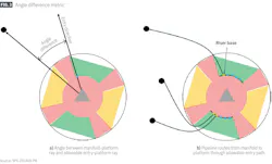
Once corridor points are established, the workflow decides which gathering points, usually manifolds, should connect to which corridor. Fig. 3 illustrates the angle difference method based on the angle defined by the directions from the platform to the gathering point (black dot) and to the corridor point (blue dot). The corridor point is the allowable pathway into the platform; therefore, a larger angle indicates a longer reach for the subsea pipeline to work its way to the entry corridor. The angle difference, therefore, provides the key metric for optimization.
The workflow computes average angle differences between each gathering point and corridor. A clustering algorithm groups gathering points to corridors while respecting the limitation that no corridor can receive more assignments than the available corridor points. This optimization balances riser distribution around the platform.
Once gathering points are grouped by corridor, the workflow determines the order in which they should connect to corridor points. Ordering is important because pipeline crossings must be avoided and routes should remain efficient. The workflow first classifies gathering points into side nodes (gathering points or manifolds) and central nodes depending on their angular position relative to the corridor’s field of view.
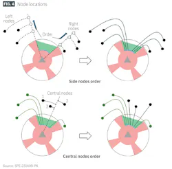
Side nodes are connected first in order of proximity to the platform because their pipelines follow corridor boundaries and are prone to interference (Fig. 4a). Central nodes follow, ordered by decreasing angle from the corridor’s centerline (Fig. 4b). This ordering ensures that pipelines fill the corridor from its edges inward, reducing risk of crossing and improving routing clarity.
The pipeline routing algorithm identifies the shortest path across a grid of bathymetry cells while avoiding prohibited areas and previously placed pipelines. Existing pipelines provide additional obstacles; thus, each new pipeline must find a distinct path without overlapping earlier ones. The algorithm proceeds sequentially through the ordered gathering points within each corridor and connects each to its assigned corridor point. The final routing output is a network of pipelines that are spatially consistent, non‑overlapping, and efficiently routed around the platform and mooring footprints.
After routing pipelines, the workflow designs risers. For catenary risers, the design includes a catenary segment suspended from the platform to the touchdown point and a straight seabed segment connecting the touchdown to the riser base (Fig. 5). The fairlead angle dictates the initial slope of the riser at the platform. The workflow identifies a touchdown point on the seabed, typically using iterative adjustments to satisfy the fairlead angle. Upon setting the touchdown point, the seabed section is drawn as a straight horizontal line at the riser base elevation. Riser construction proceeds using catenary equations.
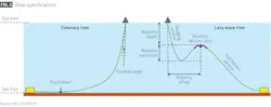
Lazy‑wave risers consist of a hanging section from the platform, a buoyancy section forming the characteristic wave, and a touchdown section joining the seabed. Four geometric parameters govern these shapes. The workflow calculates the buoyancy point location and the transition slopes between sections. If the hanging‑to‑buoyancy or buoyancy‑to‑touchdown sections do not match smoothly, the buoyancy segment is extended or modified to achieve continuity.
Workflow Test Case 1
The first test case presents a relatively simple field configuration, consisting of 12 wells feeding three manifolds which connect to a single spread‑moored FPSO in about 1,200 m of water.
Well trajectories were designed with parameters such as an 800-m kickoff distance and 2,500-m horizontal displacement. Previous optimization stages placed wells, manifolds, and the platform in feasible positions before the platform design workflow began. In this scenario, the platform orientation was 0°, and the riser base and mooring radii were set to water depth and twice water depth, respectively.
The workflow created a set of prohibited zones and three accessible corridors. It placed three corridor points in each corridor around a maximum of six riser bases. Using the clustering algorithm, two manifolds were assigned to the west corridor and one to the east. For each assigned manifold, the workflow determined the order of connection and produced pipeline routes using the optimization algorithm. These routes avoided the platform’s prohibited areas while maintaining efficient lengths. Fig. 6 shows the final arrangement. Prohibited zones on the seabed are indicated in orange.
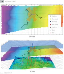
Risers were of the catenary design. Starting with a fairlead angle of 8°, the workflow found optimized touchdown points about 475 m from the FPSO, resulting in an optimized fairlead angle of 7.9°. The straight sections of the risers were drawn at the consistent elevation of the riser bases due to the model’s simplified flat seabed assumption. Although the riser design does not account for actual seabed bathymetry, most of the offshore cases have minimal variations in seabed elevation which do not significantly impact overall riser shape.
Because the optimization algorithm uses bathymetric grid representation, the grid’s resolution directly affects both computational cost and routing accuracy. To examine these effects, the workflow was run three times using the same facility layout but different map resolutions: the original resolution, a 4x enhancement, and a 16x enhancement. Increasing resolution dramatically increased the number of grid cells, which increased runtime.
Lower‑resolution maps exaggerated the size of prohibited areas due to large fully-prohibited grid cells intersecting with the boundary. As a result, pipelines routed on coarse grids tended to veer further away from mooring or riser exclusion zones. Higher grid resolution allowed pipelines to pass closer to true boundaries and provided finer maneuverability in restricted corridors.
Differences between the 4x- and 16x-enhanced maps were small, suggesting diminishing returns for higher refinements. The original or moderately enhanced resolution suffices for typical developments involving fewer than ten manifolds. Larger developments with many riser bases, tight corridors, or congested layouts, however, may benefit from higher resolution.
Workflow Test Case 2
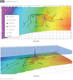
The second test case examined a more complex configuration with 16 wells and eight manifolds, again connected to a spread‑moored FPSO but rotated 60°. Lazy‑wave risers were used instead of catenary risers. The workflow started with default well placement parameters and fencing distances. Buoyancy parameters for the lazy‑wave risers were defined as ratios of depth and riser-base radius.
Buoyancy depth was 75% of water depth, buoyancy offset was half the radius, overshoot was 10% of depth, and arc radius was 5%. The workflow again generated the prohibited areas and corridors, with riser base and mooring radii matching water depth and twice water depth, respectively.
The more complex manifold placement relative to defined corridors used in this case made clustering more difficult. Some manifolds did not have a clearly preferred directional alignment with any single corridor (Fig. 7), appearing better suited to be grouped with the opposite corridor. But this would result in an unbalanced distribution, assigning one corridor more manifolds than the other. Applying a constraint to ensure that the maximum number of riser bases equaled the number of manifolds forced an even distribution, which is generally preferred in offshore developments.
After determining the manifold distribution, the workflow then determined the sequence of manifold connections within each corridor. The radial projection and angle‑based ordering methods produced a layered arrangement in which pipelines filled the corridor without crossing. Routing became more complex in this case because some routes required navigating around mooring regions or passing through more constrained corridor spaces. Regardless, the optimization algorithm produced non‑overlapping paths.

Geometric parameters produced lazy‑wave risers with realistic curved profiles originating from the FPSO and connecting to the base points (Fig. 8). All risers are identical except for minor variations in riser base elevation caused by seabed bathymetry. They did not deviate significantly from the input parameters: buoyancy points were positioned horizontally halfway between the riser base and the FPSO and vertically about 75% down between the surface and seafloor. The design also respected the specified overshoot and buoyancy arc radii.