Integrated modeling optimizes recovery for LNG assets
Based on “Integrated Field Management System for LNG Assets: Optimizing Recovery and Managing Deliverability under Complex Constraints,” SPE-202449-MS, SPE Asia Pacific Oil & Gas Conference and Exhibition, Virtual, Nov. 17-19, 2020 and “An Innovative and Practical Integrated Asset Model: Optimisation from Pore to Process with Automatic Model Update,” IPTC-21295-MS, International Petroleum Technology Conference, Virtual, Mar. 23-Apr. 1, 2021.
Integrated asset modelling (IAM) applied to gas fields supplying an LNG plant ensured that produced LNG meets contractual specifications at optimum efficiency throughout asset operating life. The system acted as a virtual advisory system to evaluate different development scenarios from infill drilling to changes in the surface network based on the plant’s requirements.
Background
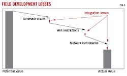
Substantial gaps occur between potential asset value and realized asset value due to suboptimal performance within reservoir, well, and network domains, and poor integration across these domains (Fig. 1). Wells, risers, pipelines, compressors, and associated processes in production networks separately affect reservoir deliverability, requiring IAM to optimize resource recovery as a unified system.

IAM clarifies understanding of mutual dependencies and system constraints along the entire production path. Constraints include fluid handling and disposal capacities, injection limits, drilling and workover rig availability, and contract rates with fluid-quality specifications.
IAM also accounts for changes during field life such as reservoir depletion, new drilling, changing fluid quality, and alterations to pipelines. Financial considerations also constrain system configuration over time. IAM includes capital expense (CAPEX) and operational expense (OPEX) factors to accelerate early production with minimum CAPEX and extend field life with minimum OPEX.
Reservoir models couple to network and facility digital twins because separate management leads to conflicts and poor matching between predictions and results. An external integrator application maintains integration and control.
Traditional IAM typically limits individual model complexity, multi-dimensional optimization, and the ability to make timely updates. To address these limitations
Schlumberger developed an advanced IAM platform.
Advanced IAM yields rapid asset optimization by combining:
- Fit for purpose modeling. Models represent subsurface dynamics and surface operations. Study objects are well-defined to ensure that the models achieve required results.
- Model integration. Existing reservoir, network, and facility models integrate into the IAM framework. Verification and consistency checks prepare IAM for total system optimization.
- Asset-level balancing and optimization. IAM supplies balancing algorithms to obey constraints and produce optimal performance using an advanced scheduler referred to as field management (FM).
- Logic framework and extensions. The logic framework, coupled with optimizers within FM, control domain models within the system. Open-source code extends the model to address specific constraints or system elements.
- Performance. IAM leverages next-generation reservoir simulation and includes unstructured domain partitioning, parallel scalability, enhanced memory management, and new-age solver techniques to enhance performance by an order of magnitude over other reservoir simulator engines.
- Rapid model update (RMU). The system rapidly updates reservoir models with production data. It assesses model quality based on key performance indicators (KPI).
Reservoir models range from decline-curve analysis production profiles, material balance tank models, and diffusivity equation-based analytical models, to full finite-difference simulators. Depending on study objectives, well and surface models range from tabulated data to advanced analytical or numeric models. The surface network similarly ranges from table-based networks to steady-state flow simulations or dynamic flow simulators.
Python extensions are available to create additional bespoke models in the network. These usually involve integrating the asset model with economic models incorporating tax and contract obligations.
The FM scheduler couples optimizers for command and control across all aspects of the integrated system. It schedules drilling and workovers based on rig availability, optimizes hydrocarbon production while honoring multiple capacity constraints throughout the system, honors operational constraints related to contractual obligations, and controls surface network and facility equipment.
Rapid model update
Component models require updates and calibrations for accuracy. The automated workflow integrates RMU into the modelling platform (Fig. 2).
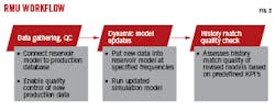
During initial configuration, a link is established between a production history repository and the reservoir simulation model. Fluid rates, volumes, phase ratios, uptimes, and well pressures are updated and mapped into the simulation’s corresponding properties. As new production data are gathered, RMU checks for quality and consistency. Inconsistencies are identified and corrected before updating the model.
Downhole logs and other surveillance data can be incorporated into the workflow. RMU requests simulated log data at required dates and compares it to measured logs. The updated model is then run to obtain new simulation results.
Once the updated model executes, RMU matches model results to production history through a range of options which include production-injection rates, cumulative volumes, ratios, water breakthrough time, and pressures. The match is judged against KPI thresholds as good, acceptable, or needing improvement (Fig. 3).
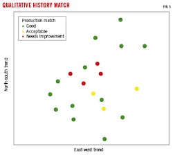
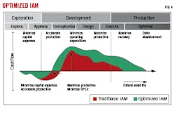
Fig. 4 illustrates the benefits of the approach over traditional field management during field development. The traditional IAM approach is highlighted in red and the new optimized IAM is in green. Optimization is achieved throughout the stages of development. At early stages, IAM minimizes CAPEX by accelerating time to production. During development, IAM unites subsurface and surface, extending production plateau while minimizing OPEX.
IAM case study
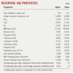
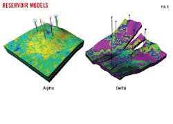
An IAM case study for an existing LNG-centered development demonstrates its capabilities. Alpha is the main gas producing reservoir, 50 km offshore in 100-m water depth. Gas is hydrocarbon rich with less than 5% CO2 and N2.
Gas from Alpha is piped onshore to a 6.5-million tonne/year (tpy) LNG plant. Initial expected operating life is 10 years based on reserves and productivity, but production data after 2 years showed a stronger than expected aquifer, and water breakthrough is now expected to limit both performance of the wells and life of the field.
To fulfill long-term contracts, an option to import gas from nearby Delta field was investigated. Delta is 35 km offshore in shallow waters and produces gas of different composition from Alpha. It is lean, sour, low-btu, and supplies an onshore fertilizer plant.
The differences between these gas compositions required the LNG plant to handle an altered gas stream. It had been originally designed for Alpha’s gas composition and the operator needed to understand how the gas stream would evolve over time to plan for modifications to handle lower-quality gas. Regardless of inlet composition, the LNG needs to remain at contractual heating values. IAM provided transient compositional tracking model studies to investigate these issues.
Additionally, the model evaluated options to optimize and extend Alpha and Delta field life with new wells, workovers, and production network alterations.
Assets
Alpha and Delta produce from sandstone reservoirs (Fig. 5). A strong aquifer supports Alpha, but Delta is on depletion drive. Gas from Delta has 43% impurities and much lower heating value than Alpha. Delta has no condensates at stock tank conditions. The Table lists reservoir and gas properties.
Alpha’s initial production was through large-bore wells gathered at a common subsea manifold connected by a riser to the Alpha platform without processing or compression. Gas is brought onshore though a 35-km subsea trunkline.
Delta has one active gas producer and an associated production platform. Gas is brought onshore through a 25-km trunkline, and a 5-km extension brings it to the LNG plant.
Gas arrives onshore at about 700 psi and passes through a slug catcher for liquids removal before entering the amine-gas treatment unit for removal of CO2. Sweetened gas passes through a separator. Molecular sieves remove water vapor to prevent hydrates in the liquefaction unit. Water handling is constrained to 12,000 b/d.
The LNG plant operates two 3.25 million tpy liquefaction trains. It uses a refrigeration loop and NGL recovery unit which strips residual methane, ethane, and LPG from separated heavier components. Methane is used for fuel gas. Ethane and LPG are reinjected into the feed stream for the main cryogenic heat exchanger (MCHE) to maintain natural gas heating values at contracted levels.
Multiple development scenarios modeled a range of field operating conditions, starting with production from Alpha only, progressing through development of Delta field, and finally simulating production from both fields with surface gas compression.
A next generation reservoir simulator modeled subsurface, a steady-state multiphase flow simulator modeled wells and surface network, and FM extended by Python modeled the LNG plant and operations. Modeling maintained constraints on the system such as reservoir deliverability, network throughput, and contractual obligations.
Production constraints
Base production targets are 920 MMscfd gas and 200,000 b/d oil. Fluctuations in plant-inlet gas composition require dynamic production profile changes to maintain contractual heating values. An optimization algorithm keeps both liquification trains operating at maximum capacity by maintaining production plateau and delaying decline via a variety of system options. Water production constraints are maintained by plugging completions with the highest water-gas ratio. Workovers are scheduled subject to rig availability constraints.
Well constraints
Production constraints were set at 200 MMscfd for all Alpha field wells and 220 MMscfd for Delta field wells. Standalone well simulations (without surface network) constrain maximum bottom-hole pressure to 1,200 psi. Simulations which include the surface network calculate bottom-hole pressure constraints from network operating pressures. A 1-MMscfd minimum economic gas production limit is imposed on all wells.
Rig, drilling constraints
Infill drilling occurs when production is less than required. It is constrained, however, by rig availability. Both fields have a dedicated rig, and each has its own average rig mobilization, drilling, and well-hookup times. These times are incorporated into the model to constrain the number and timing of workovers and new drills.
LNG plant
Flash-based Peng-Robinson equation of state (EOS) determines gas composition based on total molar rate fed into each unit at operating temperatures and pressures. FM LNG plant design incorporates the following:
- Slug-catcher. The unit removes liquids from the gas arriving onshore using a three-stage separator. Water is knocked off at the first stage. Separated condensate is combined with condensate from the immediate stripping unit and is sold.
- CO2 removal unit. The unit is part of the acid gas removal unit. Removed CO2 is transferred to a nearby field for reinjection with maximum injection capacity of 75 MMscfd.
- Intermediates stripping unit. Gas processed through the first two units is stripped of intermediates (propane, butane, pentane, and hexanes) and sent to the LPG unit. A split fraction sent to the liquification plant boosts heating values as necessary based on contract values. The optimization algorithm determines split fraction.
- Liquefaction unit. Remaining gas from the intermediates stripping unit is liquified.
- H2S removal unit. The unit removes H2S from inlet gas and processes it at the sulfur recovery unit. The amount of processed sulfur is recorded and compared among development scenarios. The user controls removal efficiency.
- Nitrogen rejection unit. The unit removes nitrogen from inlet gas and sells it to a nearby fertilizer plant. The user controls efficiency of nitrogen removal.
- Contractual gross heating for the natural is 1,150 btu/scf. Desired heating values are tuned by blending intermediates with lean gas.
FM optimization
Fig. 6 shows FM of the unit with Python extensions. The optimization algorithm maximizes LNG production while satisfying field constraints. The algorithm executes at each simulator iteration, runs LNG plant processing calculations, and compares results against target heating values and production capacity. The optimizer’s primary target is heating value. It has a ± 2 btu/scf tolerance around the contracted 1,150 btu/scf. Fractional amounts of intermediates from the intermediate stripping unit are passed to the liquification unit to meet btu requirements. The algorithm performs this function by adjusting split fraction passed to the liquification unit.
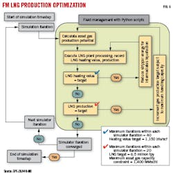
Once contracted heating value is met, the algorithm checks LNG production against the combined 6.5-million tpy production target for both liquification units, increasing or decreasing gas capacity constraints to meet this target.
Development scenarios
IAM couples the reservoir simulator to the surface network model and LNG plant processing and optimization model. FM controls each element in the individual domain models. The surface network is coupled to the reservoir model at bottom-hole conditions. Wells are solved from bottom hole to tubing head using the compositional network and are connected to flowlines varying in lengths from 3 km to 5 km before attachment to the subsea manifold. A 12-km tieback delivers production to the platform via a riser, and a 35-km trunkline delivers production to the LNG plant onshore.
Simulated development with only Alpha field production showed that surface constraints reduced LNG production plateau to 6.25 years while maintaining heating value constraints. The field was initially developed with one well, but seven infill wells were required to maintain plateau production for as long as possible.
Delta field was added into the model at the third year to extend field life in the simulation with a single producing well. Infill wells were planned when gas demand exceeded supply. Drilling schedules were based on rig availability and average drilling time constraints.
Production balance was optimized between the two fields based on fluid compositions. Lower-quality Delta gas affects heating values, requiring a balance between Alpha and Delta production with dynamic changes to intermediates fraction and gas production through FM’s optimization routine.
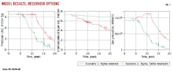
Fig. 7 shows LNG incremental production with both fields feeding the plant compared with the exclusive Alpha field simulation. LNG target rates were achieved for about 11.7 years. To satisfy btu requirements, higher production is required from both fields to account for lower-quality Delta gas. When Delta field comes online, nitrogen, H2S, and CO2 increase significantly, requiring N2 reinjection and H2S sulfur-recovery units before the fields can be integrated. H2S sulfur recovery is calculated at about 600 tonnes/day. Calculated CO2 rate at peak capacity is about 50 MMscfd, below injection constraints at the nearby field.
Surface network models studied the effects of compression on the system by either installing compressors on Alpha field platform or onshore before commingling gas with Delta field. Either option improves Alpha field recovery by limiting backpressure. Both compression scenarios use two less infill wells than non-compression scenarios. Gas production without these infill wells does not meet production targets without compression. Initial differential pressure across the compressors is 50 psia and can be adjusted incrementally as required to 400 psia, with 30 days minimum time difference constraint between changes.
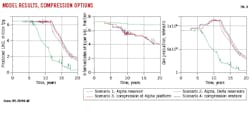
Onshore compression is better than at the platform because it also improves Delta field’s incremental production. Both compression schemes add about one additional year to the production plateau, from 11.7 to 12.5 years (Fig. 8). Incremental LNG production with onshore compression is about 3.7 million tpy. Economic viability of compression can be evaluated based on this estimate.
Bibliography
Biniwale, S., Ali, S., Khan, O.H., Zhou, W., Efimova, K., and Takahashi, M., “An Innovative and Practical Integrated Asset Model: Optimisation from Pore to Process with Automatic Model Update,” IPTC-21295-MS, International Petroleum Technology Conference, Virtual, Mar. 23-Apr. 1, 2021.
Khan, O.H., Ali, S., Elfeel, M.A., Biniwale,S., and Dandekar, R., “Integrated Field Management System for LNG Assets: Optimizing Recovery and Managing Deliverability under Complex Constraints,” SPE-202449-MS, SPE Asia Pacific Oil & Gas Conference and Exhibition, Virtual, Nov. 17-19, 2020.
Tahir, S. and Kindi, S.A., “A Top-Down View of Field Development Plans, Integrated Reservoir Performance and Production Sustainability Assurance,” SPE-197379-MS, Abu Dhabi International Petroleum Exhibition & Conference, Abu Dhabi, UAE, Nov. 11-14, 2019.
Zhou, W. Ali, S., and Biniwale, S., “Openness in Reservoir Simulation: Empowering Flexible Field Management,” SPE-202303-MS, SPE Asia Pacific Oil & Gas Conference and Exhibition, Virtual, Nov. 17-19, 2020.