3D horizontal trajectory reduces drilling cost
Boyun Guo
Nawab Sohail
University of Louisiana at Lafayette
Efficient drilling in shale reservoirs requires detailed 3-dimensional (3D) horizontal well trajectories. An orthogonal-arc trajectory (OAT) method assumes a single constant curvature in the curved sections of the borehole and only requires simple, cost-effective deflection tools with constant dogleg severity. Closed-form OAT equations and a practical application demonstrate how the method reduces drilling costs and simplifies operations.
Trajectory calculations
Well trajectory directly affects drilling efficiency and cost. Efficient well trajectories enable access to target reservoirs while minimizing risks associated with equipment malfunction and unexpected geological formations.1 2 In past decades, various 3D well trajectory approaches have shown distinct advantages and disadvantages.3 The radius-of-curvature trajectory method (RCM), favored for horizontal wells and extended reach operations, maintains a constant build-rate for the inclination angle and a variable turn-rate for the azimuth angle.4 5 Well trajectory computations based on these angles at the upper and lower ends of the well path provide accurate calculations for north, east, and true vertical depth (TVD) between directional survey stations.6
Python programming and other software tools maximize computation efficiency for reliability-centered maintenance (RCM) and include real-time options for altering drilling approaches.7 Despite these improvements, radius-of-curvature trajectory calculations must be used with caution in high dogleg-severity cases to ensure accuracy.8 Engineers must understand their limitations for proper use according to individual drilling requirements.9
The constant-turn-rate method (CTRM) assumes constant build-rate and turn-rate.10 Its predictability helps with operational efficiency, most prominently in less complex geology. In most cases, it cannot respond effectively to unexpected variation in character of formation or in overcoming obstacles. Its inflexibility can result in less preferable drilled solutions and increased operational risk. The method typically produces higher dogleg severity compared with other techniques, leading to increased mechanical loads on the tools.11
Poor optimization is one of the biggest weaknesses of CTRM. Although effective in general path planning, it can produce a less efficient path-to-target in contrast with complex techniques using real-time analysis and adaptable algorithms.12 Alternatively, a minimum curvature method (MCM) provides a standard for borehole coordinate (drilled-well path) calculations from directional survey data.13-15
All these types of well trajectories have varying curvatures. They can be drilled with modern deflection tools such as AutoTrak, Power Drive Orbit, and Geo-Pilot. These tools, however, are not economical for most small operations for which drilling expenses are 40–50% of total exploration and production costs.16 17
A constant curvature trajectory can also provide easy drilling with conventional deflection tools such as bend-sub and bent-housing motors. This technique drills the well safer by producing low friction, drag, and torque. Constant curvature trajectory calculations, however, require difficult numerical integrations (OGJ, Apr. 19, 1993).
This article proposes an orthogonal-arc trajectory which assumes a single constant curvature in the curve sections of the borehole, using simple deflection tools with constant curvature to reduce drilling costs. Equations for designing constant-curvature well trajectories are closed form, making the calculations straightforward.
OAT
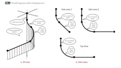
Fig. 1 shows the OAT approach. The 3D well trajectory includes a vertical section at top, an upper arc section in a vertical plane, a lower arc section in a space plane, and a slant-horizontal section at bottom. Equations for designing the kick-off point (KOP) and coordinates of trajectory in the upper and lower arc sections are in the Equations box.
Trajectory calculations
Equations 1 and 2 derive an expression for the depth of KOP based on side views in Fig. 1. The deflection tool’s full angle-changing capability builds inclination in the upper arc section. Equations 3-5 calculate inclination angle build-rate.
Likewise, the deflection tool builds both inclination angle and azimuth angle in the lower arc section. Equations 6 and 7 determine the inclination angle and turn rate when using constant build rate (B2avg) in the lower arc section, respectively. B2avg is numerically determined to reach target depth. Equations 8-15 express east (Ei), north (Ni), and vertical depth (Zi) coordinates at point i based on the minimum curvature theory for both upper and lower arc sections.
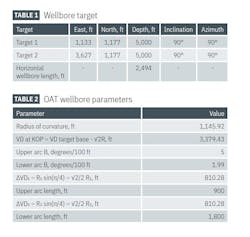
Table 1 presents data which define a horizontal well trajectory to reach two targets at the heel and toe of a horizontal well. Table 2 summarizes design parameter values to achieve the well trajectory. Fig. 2 shows the designed well trajectory in 3D.
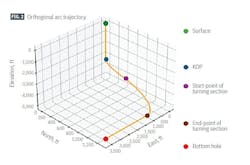
This calculation demonstrates the practical application and key advantages of OAT for 3D horizontal-well planning. Using parameters outlined in Tables 1 and 2, OAT designed a complex well path which reached both heel and toe targets using two arc sections with constant curvature.
All required coordinates derive from closed-form equations, eliminating the need for iterative numerical integration common in traditional methods. The calculations occurred rapidly and with minimal computational resources.
References
- Abughaban, M.F., Bialecki, B., Eustes, A.W., John P. de Wardt, J.P., and Mullin, S., “Advanced Trajectory Computational Model Improves Calculated Borehole Positioning, Tortuosity and Rugosity,” SPE-178796-MS, IADC/SPE Drilling Conference and Exhibition, Fort Worth, Tex., Mar. 1-3, 2016.
- Mahmoud, H., Hamza, A., Nassar, M.S., Hussein, I.A., Ahmed, R., and Karami, H., “Hole cleaning and drilling fluid sweeps in horizontal and deviated wells: Comprehensive review,” 106748, Journal of Petroleum Science and Engineering, Vol. 186, March 2020.
- McLeod, D. and Billger, D., “Comparing multishot & continuous surveys using the TwinGyro™,” Coring Magazine, Apr. 24, 2020.
- Wilson, G., “Radius Of Curvature Method For Computing Directional Surveys,” SPWLA-1968-D, SPWLA 9th Annual Logging Symposium, New Orleans, La., June 23-26, 1968.
Halafawi, M. and Avram, L., “Wellbore trajectory optimization for horizontal wells: the plan versus the reality,” Journal of Oil, Gas and Petrochemical Sciences, Vol. 2, No. 1, February 2019. pp. 49-54. - Jin, L. and Wei, J., “Research on Horizontal Directional Drilling (HDD) Trajectory Design and Optimization Using Improved Radial Movement Optimization,” Applied Science, Vol. 12, No. 23, Nov. 29, 2022, p. 12207.
- Mertoglu, O., Bakir, N., and Kaya, T., “Geothermal applications in Turkey,” Geothermics, Vol. 32, No. 4-6, August-December, 2003, pp. 419-428.
Krechowicz, M., “Comprehensive Risk Management in Horizontal Directional Drilling Projects,” Journal of Construction Engineering and Management, Vol. 146, No. 5, Feb. 22, 2020, p. 04020034. - Armitage, C. J., “Streamlined RCM Process for Drilling Equipment,” OTC-15339-MS, Offshore Technology Conference, Houston, Tex., May 5-8, 2003.
- Planeix, M. Y. and Fox, R. C., “Use Of An Exact Mathematical Formulation To Plan Three Dimensional Directional Wells,” SPE-8338-MS, SPE Annual Technical Conference and Exhibition, Las Vegas, Nev., Sept. 23-26, 1979.
- Guo, B., Miska, S., and Lee, R. L., “Constant Curvature Method for Planning a 3-D Directional Well,” SPE-24381-MS, SPE Rocky Mountain Regional Meeting, Casper, Wyo., May 18-21, 1992.
- Topolski, T., Gonet, A., and Stryczek, S., “Analysis of inaccuracy of determining a directional borehole axis,” AGH Drilling, Oil, Gas, Vol. 32, No. 3, January 2015, p. 589.
Taylor, H. L. and Mason, C. M., “A Systematic Approach to Well Surveying Calculations,” SPE Journal, Vol. 12, No. 6, December 1972, pp. 474-488.
Zaremba, W. A., “Directional Survey by the Circular Arc Method,” SPE Journal, Vol. 13, No. 1, February 1973, pp. 5-11. - Sawaryn, S.J. and Thorogood, J.L., “A Compendium of Directional Calculations Based on the Minimum Curvature Method,” SPE Drilling and Completions, Vol. 20, No. 1, March 2005, pp. 24-36.
- Brun, A., Aerts, G., and Jerkø, M., “How to achieve 50 percent reduction in offshore drilling costs,” McKinsey & Co., Oil & Gas, 2015.
- Wethe, D., “Shale Costs Forecast to Fall 10% This Year, Wood Mackenzie Says,” GoHaynesvilleShale.com, July 29, 2024.
Authors
Boyun Guo ([email protected]) is a professor and graduate coordinator in the department of petroleum engineering, University of Louisiana at Lafayette. He holds a Ph.D. in Petroleum Engineering (1992) from the New Mexico Institute of Mining and Technology. He is a member of the Society of Petroleum Engineers (SPE).
Nawab Sohail ([email protected]) is a Ph.D. candidate in the department of petroleum engineering at the University of Louisiana at Lafayette. He holds a BE (2015) and ME (2019) from Mehran University of Engineering and Technology, Pakistan. He is a member of SPE, American Association of Professional Geologists (AAPG), and the Society of Petrophysicists and Well Log Analysts (SPWLA).