Erosion-resistant screens protect Alaska North Slope wells
Chris Malbrel
TPM Ltd.
Houston
Todd Sidoti
Hilcorp Alaska LLC
Anchorage
Howard Bonhomme
EnerG Screens LLC
Houston
Cased-hole completions using standalone screens (SAS) for sand control frequently experience erosion. Hilcorp Alaska LLC ran a novel erosion-resistant screen in its Prince Creek formation completion at Milne Point to produce sand-free water for pad injection.
The screens covered 300-ft in a slanted interval with lower cost and risk than a gravel pack. The well produced at more than 5,000 b/d and did not experience erosion. Based on these results, Milne Point injection well completions will include 4 ½-in. and 2 ⅜-in. screens equipped with the anti-erosion design.
Alaska waterflooding
Large heavy oil reserves exist in the North Slope of Alaska, but the usual thermal recovery methods risk melting the permafrost, producing negative surface effects due to the shallow location of the reserves.
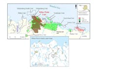
Polymer injection tests in Canada led Hilcorp Alaska to avoid thermal problems associated with steam recovery. A pilot started in 2018 quickly scaled up to about 60,000 b/d of polymer injection through 50 injection wells. Fig. 1 shows this onshore Milne Point project on the edge of the Arctic Ocean.
Initial field production started in 1985 and maximized at 60,000 b/d in 1995. By 2012, production decreased to 17,000 b/d. With the injection program, the field currently produces 43,000 b/d.
Water for injection in Milne Point field produces from a clean, low-salinity shallow aquifer which requires only low polymer concentrations to develop the proper viscosity. It also does not form a sludge with solids and oil as experienced with produced water. Gravel packing has long been standard practice for completing water source wells.
When the electrical submersible pump (ESP) pump failed in the E-pad water source well, and a partial casing collapse caused by subsidence limited access to the well, water for continued polymer injection required a new water source. Well E-23 offered the best option after reviewing shut-in wells on the pad.
This well had initially been drilled to target the deeper Kuparuk formation and inject water into a deep horizontal section. A plug-and-abandon operation in the Kuparuk zone allowed for reperforation across the shallower Prince Creek fine formation in the slanted section of the well at a 45-50° angle.
Slant well (30-70°) cased-hole gravel packing (CHGP) difficulties relative to vertical-well gravel packing include additional complexity and operational costs. The intermediate angle also induces proppant settling on the low side of the well, uneven filling of perforations, and voids which amplify uneven flow distribution in the annulus leading to screen erosion and completion failure. For these reasons, gravel packing was not a suitable option for this workover.
SAS completions using premium mesh screens successfully control analog sands in oil producers with less installation cost and risk than CHGP, but cased hole completions with SAS frequently experience erosion. Several concepts exist for screen erosion resistance, including new erosion-resistant materials such as ceramic or metal-hardened meshes by coatings or special heat treatment (boronizing, carburizing, etc.).
These options provide alternative preventative solutions to erosion and expand usage of screens in completions without the protection of gravel packs. They are often expensive, however, and may suffer from poor plugging resistance, flow distribution, corrosion, or mechanical resistance.
To address this issue, a Prince Creek trial completion ran a novel erosion resistant screen with an inner shielded screen to rapidly return polymer injection to the well pad. The design minimized screen erosion damage in this cased-hole environment.
Shielded screen design
Screen erosion in cased-hole completions reveal failures near basepipe perforations with signs of localized erosion (e.g. enlarged perforations) starting inside the screen and moving outward. These observations included both wire wrap and mesh screens, and recent pilot-scale erosion testing confirmed these findings.
To prevent this erosion mechanism, the novel screen incorporates an inner shield above the basepipe perforation to prevent line-of-sight flow towards the perforation underneath the screen jacket. This design protects the mesh screen jacket above the shield from fluid flow convergence towards basepipe perforations.
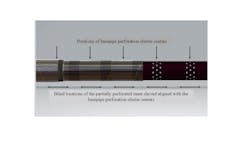
Fig. 2 shows the full-screen design for the shielding shroud strategically located between the screen assembly and the perforated basepipe. The partially perforated inner shielding shroud locates blind sections directly over the perforation clusters. This design shields the screen jacket from erosive eddies generated by flow convergence at the basepipe perforations, forces fluid flow to distribute over a larger filter area in a stand-alone configuration and reduces fluid velocity going through the mesh layers.
The shielding damps fluid flow during startup and minimizes formation sloughing from the perforations. Gradual startup further protects the screen by preventing screen-plugging from formation sand during initial stages of production.
The screen was subjected to the full array of screen qualification testing as suggested by API 19SS Standards. Results conformed to performance recorded for the standard mesh screen, confirming that the addition of the innermost shroud did not affect the mechanical integrity of the screen.
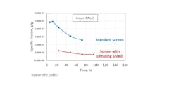
Comparative erosion tests between the new design and standard mesh screen construction used 4-in. diameter screen coupons representing both designs. Screen erosion was performed by pumping a 4-g/l. slurry of 25 mm silicon carbide in water through the screens at 72 gpm. Intermittent coupon inspection measured specific erosion damage (screen weight lost relative to erosive material weight passed through the screen, g/g) during exposure time.
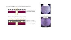
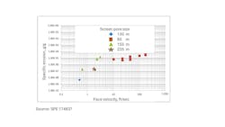
Test results showed that specific erosion of the standard mesh screen sample matched similar mesh screen constructions reported in the literature (Fig. 3). The inner shielded screen design, however, resulted in more than a 4x reduction in specific erosion under the same conditions (Fig. 4).
Based on a velocity-dependent erosion wear-rate equation, the new screen design upgrades the screen face velocity limit to 0.20 ft/sec from 0.13 ft/sec for standard standalone completions (Fig. 5). This improvement provides either a significant improvement in the safe operating envelope or may be converted into a 50% higher production limit.
Field deployment
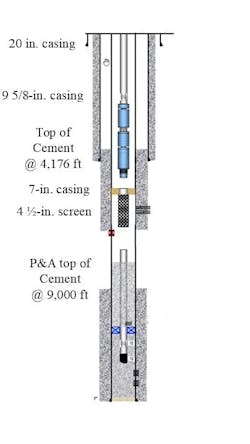
Before recompleting the new interval at the Milne Point project, the lower zone needed to be abandoned by perforating the tubing above the packer, circulating cement to plug the zone, and cutting and pulling the tubing out of the well. The upper zone was then perforated overbalance using a 0.42-in. x 6 shots/ft perforation scheme over two zones for a total of 290 ft. Screen was set across the zone and held in place using a 7-in. x 4-in. permanent packer before installing the ESP pump (Fig. 6). About 250 ft of rathole was left below the screen as a sump.
The erosion-resistant screen was successfully deployed over the interval, and a 5,000-b/d production rate was established. The completion cost was a fraction of the cost of a gravel pack completion. High fluid-velocity emerging from casing perforations diffused across a larger screen section available without a gravel pack, and flow convergence at basepipe holes did not cause erosion of the mesh screen above the diffusion layer. The lower average velocity across the screen reduced plugging risk from formation sand.
Downhole gauge monitoring showed minimal changes in skin conditions, and the ESP current draw showed no unusual fluctuations. Encouraged by these results, additional wells will employ the same approach but extend to longer lengths to accommodate high production rates at a higher deviation (about 70°).
With more than ten water source wells completed in the region utilizing gravel packs, performance benchmarking of the SAS completion determined that future Milne Point wells will be completed with 4 ½-in. and 2 ⅜-in. SAS completions equipped with the inner shield. The successful deployment of these screens in this application has led to additional deployments in deepwater subsea wells offshore Brazil.
Bibliography
Aitkulov, A., Edwards, R., Redwine, C., and Cunha, K., “Milne Point Field Polymer Flood Update and Further Expansion,” SPE-218269-MS, SPE Improved Oil Recovery Conference, Tulsa, Okla., Apr. 22-25, 2024.
Malbrel, C.A. and Kale, R., “Time Lapse Wear Study Yields New Design Features to Improve the Erosion Resistance of Stand-Alone Screen Completions,” SPE-208817-MS, SPE International Conference and Exhibition on Formation Damage Control, Lafayette, La., Feb. 23-24, 2022.
Procyk, A., Gou X., Marti S.K., Burton R.C., Knefel, M., Dreschers, D., Wiegmann A., Cheng L., and Glatt E., “Sand Control Screen Erosion: Prediction and Avoidance,” SPE-174837-MS, SPE Annual Technical Conference and Exhibition, Houston, Tex., Sept. 28-30, 2015.
About the authors
Chris Malbrel is the director of corporate development at Tubular Perforating Mfg. (TPM) in Houston. He holds a BS in geology (1985) from Ecole Nationale Supérieure de Géologie and a Ph.D. (1990) in mineral engineering from Columbia University. He is a member of the Society of Petroleum Engineers (SPE).
Todd Sidoti is a wells engineer for Hilcorp in Anchorage. He holds a BS in electrical and electronics engineering (2000) from Purdue University.
Howard Bonhomme is a sand control consultant in Houston. He holds a BS (1993) from the University Lafayette Louisiana.
