Novel muds extend HPHT drilling, reduce leakoff
Based on “Drilling Fluids Design and Field Deployment for the First HPHT Deepwater Production Project in the US Gulf of Mexico,” IADC/SPE-208668-MD, SPE/IADC International Drilling Conference and Exhibition, Galveston, Tex., Mar. 8-10, 2022, and “Water-Based Drilling Fluid for Controlling Deep-Reservoir Extreme Conditions in an Abu Dhabi Gas Shale Play,” SPE/AAPG/SEG Asia Pacific Unconventional Resources Technology Conference, virtual, Nov. 16-18, 2021.
Optimized oil-based and water-based drilling muds formulated for high-pressure, high-temperature (HPHT) service in the Gulf of Mexico (GOM) and Abu Dhabi prevented barite sag while delivering low equivalent-circulation densities (ECDs) and low leakoff.
Schlumberger Ltd. formulated an invert emulsion mud system for the intermediate hole and reservoir sections of the first GOM deepwater HPHT production project to receive US government approval. Synthetic-based mud (SBM) properties were adjusted to provide adequate sag and rheology with minimal formation invasion and damage. While typical HPHT drilling muds derive from existing uphole conventional temperature and pressure mud systems, this system was specifically designed and mixed for HPHT service. The mud was deployed in the field, with successful mixing, shearing, and screening at the local mud plant (LMP). It maintained high stability during the drilling campaign.
TotalEnergies SE successfully used water-based mud in pilot hole and reservoir sections of a four-well campaign in Block 1, Divab field, north central UAE. All reservoir sections were successfully drilled and evaluated. Five coring runs using this mud were performed on an appraisal with 100% core recovery.
GOM SBM
In the US, the Bureau of Safety and Environmental Enforcement (BSEE) defines HPHT in the Gulf of Mexico as greater than 15,000 psi at the wellhead and more than 350° F. reservoir temperature. The first HPHT project in the GOM to receive BSEE approval used an invert emulsion fluid (IEF) for drilling the intermediate section and an SBM for the reservoir. Emulsifier packages and weighting material were optimized to maximize long-term sag stability, with static aging up to 28 days. Fluid-loss reducers maintained emulsion stability. The mud produced stable filter cakes, maintaining fluid loss for more than 16 hr at > 350° F., significantly longer than the typical industry-standard 30-min test period.
Increasing fluid loss and sag performance can adversely affect rheological properties, however, and increase ECD. This was addressed by adjusting rheological agent type and concentrations and incorporating two unique fluid-loss control additives.
Two types of SBM were developed for the reservoir. An HPHT reservoir drilling fluid (RDF) drills the pay zone and lays a filter cake on the formation. After drilling, a screen-running fluid and suspension fluid (SRF-SF) displaces RDF and suspends the hole with clean mud for running the stand-alone screen (SAS) assembly. RDF and SRF-SF are optimized to prevent formation damage or screen plugging. The clean mud is left static in the wellbore for up to 28 days before well test or production.
Typical HPHT drilling uses the existing uphole mud system, formulated for conventional temperatures and pressures with conventional emulsifiers and wetting packages. The mud is reformulated on the rig with additives to handle HPHT sections. By contrast, the mud for the HPHT GOM application was made from scratch, exclusively for HPHT service.
IEF intermediate mud
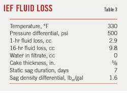
The fluid was designed to perform as a low-ECD drilling fluid with long-term sag stability and comply with stringent long-term HPHT fluid loss. For sag stability, the IEF was required to have a bottom layer density < 1.0 pound per thousand gallons (lbm/gal) more than original mud density after 16-hr aging in an API aging cell at 330° F. After 7 days of aging, it had to have a bottom-layer density < 1.5 lbm/gal above original mud density. Fluid loss on a low-permeability ceramic disk at bottom hole static temperature (BHST) and 500 psi needed to be under 4 cc/hr, and the mud needed to pour smoothly out of the HPHT cell.
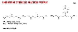
Emulsion stability was achieved with an amidoamine emulsifier which had a modification to maleic anhydride in the manufacturing process to improve the reaction pathway and yield a more efficient emulsifier (Fig. 1).1 Typically, traditional synthesis of amidoamines suffers from incomplete maleic addition. A dedicated oil-wetting agent was used as a secondary emulsifier package. The emulsifier and wetting package combined to produce a stable emulsion under test conditions.
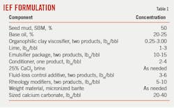
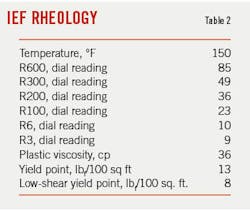
Additional additives reduced low-temperature rheology without compromising drill cutting carrying capacity. The IEF was evaluated at 360° F. in a 7-day static test as a contingency case in which fluid might encounter deeper, hotter sections for non-producing and injection wells. Sag was minimized using micronized barite paired with viscoelastic improvement with inorganic and polymeric rheological modifiers. An organo-soluble swellable polymeric agent with oil-dispersible product ensured low fluid loss. Table 1 shows the IEF generic fluid formulation and Table 2 lists main fluid properties.
Reservoir fluids
RDF sag requirements equaled IED fluid requirements. Allowable free-oil separation was set at maximum 20% by volume. Fluid loss on a low-permeability ceramic disk at BHST and 500 psi needed to be under 10 cc/hr, and the mud needed to pour smoothly out of the HPHT cell. Maximum allowable 16-hr filter cake thickness was ⅜ in. The filter cake had to flow back or be permeable to production after exposure for 60 days at bottomhole conditions. Both RDF and SRF-SF had to be mobile after a 28-day static-heat aging period at BHST.
Additional concerns for SRF-SF beyond those for intermediate IEF are spotting without causing high ECDs and low surge and swab pressures while running in hole. Formation damage also must be minimized by maintaining emulsion stability, with no brine breakout in the fluid after 60 days at BHST.
A production screen test (PST) checked compatibility of the wire wrap screen in the SAS completion to SRF-SF. Four liters of fluid were run sequentially through a 10-gauge wire-wrapped screen sample at 10 psi. The first liter had to pass through the screen for a successful test. Plugging tendencies were indicated by the time to pass the remaining 3 l. compared with the first liter.
Extended exposure of bottomhole conditions on the SRF-SF required a different emulsifier package than in IEF. Time and temperature significantly degrade amidoamine emulsifiers, and formation damage and well control are put at risk using this emulsifier in this application. A non-amidoamine (non-nitrogen) surfactant was substituted with a dedicated wetting agent to account for smaller particle sizes (D90 < 10 mm) in the weighting material than are traditionally used.
The fluid-loss control comprised two polymers and an organophilic quebracho tannin fluid-loss agent. One of the polymers swells in a nonaqueous environment and deforms reversibly under shear to create a thin, pliable filter cake when combined with other agents. A modified HPHT cell with a low-permeability ceramic disk matched to formation data tested the fluid in the lab and field. Filtrate was collected at 1, 30, and 60 min, and 16 hrs.
To prevent barite sag, fine micronized barite (D90 < 10 mm) served as the weighting material, and a hectorite-based organophilic clay developed for HPHT applications provided primary viscosity. A supplemental rheology modifier also prevented sag by improving ultralow shear-rate viscosity and fluid carrying capacity. Static sag tests performed at 7, 14, and 28 days at 350° F. showed that the fluid performed within static shear value, free oil, and delta density specifications.
An additional contingency test determined screen plugging, in case settled barite flowed back through the screen. A 500-cc modified HPHT cell containing 350 ml SRF-SF and a wire-wrap screen coupon instead of a ceramic disk was heated to 350° F. with 200 psi backpressure on the headspace of the cell. The cell was left to static-age for 28 days. After the shut-in period, the cell cooled to 180° F. followed by depressurizing the headspace to ambient pressure. The bottom valve was opened, and fluid flowed through the screen at 10-psi head pressure. The entire 350-cc sample volume flowed freely through the wire-wrapped screen coupon.
A permeability plugging test (PPT) quantified RDF formation damage. The test uses aloxite core or low-permeability Berea Buff to simulate the formation. A 16-hr filter cake was built by RDF leakoff through the core. RDF was displaced by SRF-SF followed by a 5-day running period and 60-day suspension period simulation. Core and screen damage were measured by back flowing filter cake off the core and through a 10-gauge screen coupon. The RDF met specifications consistently with both lab and field samples.
Field deployment
Building IEF with seed mud from previous intervals reduced mixing times at the liquid mud plant (LMP) and allowed building more compatible volumes as needed. Compatibility also maximized rig-storage volumes because IEF was combined with the uphole low-ECD SBM when drilling operations concluded.
IEF was also used as the reservoir drilling fluid for an injector well. This was not its original purpose, but the rheological properties fit the application, which was a cased and perforated completion. Flowback through screens and filter-cake liftoff were not required. IEF was used in the final two drilling intervals with only slight viscosifier treatment necessary for logging and casing running. The fluid used pneumatically conveyable fine-ground barite instead of micronized barite, resulting in quick density changes between intervals.
Building RDF from scratch at the LMP and shearing it ensured yielding of the products. A series of yard tests ensured that mud batches had comparable properties to lab-mixed fluids. Following shearing to ensure yielding of products, the fluid was screened through shale shakers to ensure it passed through screens in the SAS completion. Fluids were loaded on boats which had been thoroughly cleaned.
Fluid was agitated in the previously cleaned rig pits for several hours and checked for PST by the 3-l. screening test. Fluid which did not pass the test or showed significant increases in flow-through time for the second or third liter of fluid was rescreened over shakers. PST quality was difficult to maintain during drilling. Keeping shaker screens in required condition was costly and labor-intensive because the required finer-mesh screens needed frequent replacement. In addition to monitoring shakers, 4-l. PSTs were run on a set schedule based on time and footage drilled, and any failure or plugging tendency required an immediate pause in drilling to inspect the shaker screens. Ultimately, remedial screening sessions did not impact the critical operation path.
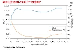
Monitoring of fluid electrical stability (ES) and HPHT fluid-loss stability occurred during temperature fluctuations from reservoir temperature to cold-riser temperatures. ES is an indicator of emulsion stability and HPHT fluid loss is an indicator of filter-cake quality. ES was also checked multiple times per tour and continuously upon return to circulation from a static period. Fig. 2 shows stable ES over a 59-hr static period.
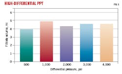
HPHT fluid loss was checked on the rig with 500-cc HPHT filter press kits with ceramic cores to perform multiple 16-hr modified HPHT fluid-loss tests at a time. Filtrate was monitored for free water, and filter cake was measured for thickness. In addition to the modified HPHT filtration testing, PPTs were conducted on field samples during drilling because of potentially high reservoir depletion. Filtrate results after the 6-hr testing period up to 4,000 psi were consistent within experimental error (Fig. 3).
Building SRF-SF fluid from the RDF formulation with additional organophilic clay allowed for wireline logging and the SAS run. The fluid was homogenized for several hours and sheared to mix products thoroughly. A PST test was performed, and the fluid was reprocessed over shakers if needed.
Proprietary hydraulics modeling software simulated fluid behavior in the well. HPHT rheology measurements estimated fluid response under downhole conditions. Static temperature modeling determined safe tripping scenarios for downhole tools and screens. Calculations of ECDs, surge-swab pressures, and break-circulation ensured all were within operating limits.
Particle size distribution (PSD) was analyzed in laboratory and LMP field-mud samples to ensure that particles would not plug the screen. This was done in addition to the PST to monitor changes in fluid quality that might not be picked up by the plugging test. In addition, individual additive grind sizes such as micronized barite and fluid-loss reducers were tested to ensure meeting strict PSD specifications were followed.
A technical service engineer (TSE) assigned to the project provided technical support with lab work and software modeling. The TSE also traveled to the field to supervise yard mixes, full mud volume mix at the LMP, and drilling operations, train field engineers, and collect samples at various points in the drilling process for laboratory evaluation.
Abu Dhabi WBM RDF
TotalEnergies, operator of Block 1 in prospective unconventional Diyab formation, onshore north-central UAE, required a water-based drilling fluid to comply with environmental regulations. WBM are typically limited for high-temperature service, however, because they contain biopolymers for viscosity, solids suspension, and fluid-loss control which become unstable at temperatures exceeding 300° F. Gellation is difficult to control for high-density fluids and restarting circulation to overcome gel strength can require excessive pressures, resulting in formation breakdown and lost circulation. TotalEnergies needed to develop a WBM that had the same properties as invert-emulsion drilling fluids.
Diyab formation
Diyab formation has lower porosities, higher-carbonate mineralogy, and a higher pressure gradient than typical shale formations. The depth of the prospective basal Diyab interval across Block 1 ranges between 3,758 m and 4,115 m.
Unconventional offset wells (DE-02, DE-03, and DE-04) were originally drilled by ADNOC to test the productivity of three sub-members of the greater Diyab interval (Jubaila, Hanifa, and Tuwaiq Mountain formations). Hanifa looked most promising, and TotalEnergies subsequently drilled DE-05, the first appraisal horizontal well targeting the Hanifa formation, followed by DE-06. Two deep wells, DE-09 and DE-10, were also drilled and evaluated.
Fluid validation
The ADNOC offset well muds had barite sag, fluid degradation, and well control issues. WBM RDF was therefore designed to minimize ECD from mud gelation, maintain solids suspension to prevent sagging, maintain stability during long open-hole exposure time, and be impervious to H2S found in Arab formation at 3,450 m. The mud properties were formulated with the following objectives:
- Stable at 330° F. for 7-days static conditions with acceptable sag index.
- Excellent hole-cleaning rheology while minimizing ECD and losses while drilling.
- Inhibited against reactive shale formations.
- Resistant to solids and cement contaminations.
- Comparable coefficient of friction to synthetic-based drilling fluids.
- Easy mixing on location if additional volume is required to compensate for losses.
- Lower cost per barrel compared with synthetic-based drilling fluids.
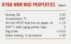
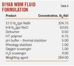
Table 4 lists the required conditions and mud properties for the Diyab campaign and Table 5 lists the fluid formulation. This formulation resulted in a final brine density of 1.44 specific gravity (SG) and a mud weight (MW) of 1.92 SG. The mud passed all rheology and fluid-loss requirements. Sag also met requirements, with 0.504 sag factor at 90° and 45° cell inclinations.
Field application
WBM use occurred in the 8 ½-in. vertical pilot hole and 90° horizontal reservoir sections of the four-well appraisal campaign. Well-build angles ranged from 25° to 30° until horizontal, then continued laterally for 2,000 m up to rig-pump pressure and torque limits. Problems for the mud system in these wells included cuttings transport out of the well and long open-hole formation exposure times during logging and temporary suspension. Managed pressure drilling (MPD) equipment was available on stand-by for potential well-control events requiring high mud weights to continue drilling.
Ideal reservoir section drilling used a single bottom-hole assembly (BHA). Drilling of the reservoir section for wells DE-05 and DE-06 used 1.80 SG mud. Well DE-05 was drilled without incident.
The primary objective of Well DE-06 was to land within the Hanifa formation and geosteer a 2,000-m horizontal drain within that formation. The well was drilled to a depth of 6,039-m MD rKB (3,817.9-m TVD) but encountered a mechanical stuck-pipe event during back-reaming due to a high pore-pressure section after reaching TD. The MPD was used on Well DE-06 side-track and required 2.40 SG mud-weight kill fluid with an increased NaBr-NaCl ratio and ultrafine grind barite. Drilling DE-06 sidetrack (DE-06 ST) ahead to a depth of 6,120-m MD (3,867.7-m TVD) required 2.2-SG mud made from a higher NaCl-NaBr ratio, and this mud was subsequently used in wells DE-09 and DE-10. Fig. 4 compares required mud weights between DE-05, DE-06 ST, and DE-06 kill-weight mud.
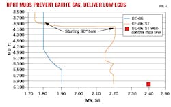
Maximum temperature recorded with logging-while-drilling (LWD) tools in Well DE-05 was 314° F. at 3,828-m TVD, higher than the average 300° F. observed in offset wells. From DE-06 temperature profiles, the static formation temperature in Hanifa formation was estimated to be about 330°F.
Lessons learned from this campaign included:
- Recycling drilling fluid from well-to-well produced a mature fluid with increased low-end rheology while maintaining low PV and ECD parameters despite mud weights greater than 2.0 SG. Hole cleaning was improved while avoiding entire fluid losses to the reservoir.
- Addition of the powder lubricant to the system did not significantly improve lubricity of the 2.2 SG high-weight brine and polymer mix.
- Influx of formation gas in an elevated-rheology polymer drilling fluid will impact gas release at surface.
All reservoir sections were successfully drilled and evaluated despite the DE-06 well-control issue. Five coring runs were performed on the DE-10 appraisal with 100% core recovery.
Reference
- Khramov, D., Khvostichenko, D., Okhrimenko, A., Vickers D., and Barmativ, E., “Designing Advanced Emulsifiers for High-Performance Synthetic Fluids: From Drawing Board to the Challenging Wells,” AADE-20-FTCE-085, 2020 AADE Fluids Technical Conference and Exhibition, Houston, Apr. 14-15, 2020.
About the Author

Alex Procyk
Upstream Editor
Alex Procyk is Upstream Editor at Oil & Gas Journal. He has also served as a principal technical professional at Halliburton and as a completion engineer at ConocoPhillips. He holds a BS in chemistry (1987) from Kent State University and a PhD in chemistry (1992) from Carnegie Mellon University. He is a member of the Society of Petroleum Engineers (SPE).