Long conventional horizontal fracturing produces significant erosion
Hydraulic fracturing in long horizontal wells exposes completion equipment and surface frac iron to significant proppant-induced erosion. Field observations and laboratory studies showed that erosion depends on fluid velocity, equipment geometry, proppant size, concentration, and particle shape.
Case studies revealed severe erosion of isolation sleeves, frac sleeves, and completion components leading to sleeve collapse, flow restrictions, and failures to open fracture stages. Unlimited frac sleeve systems can improve efficiency and increase stage counts, but they also amplify erosion risks throughout the completion system.
Generic erosional velocity limits, such as API RP 14E, provide insufficient protection from erosion because erosion susceptibility varies by component and operating conditions. Effective mitigation, therefore, includes optimizing fluid rheology, proppant selection, pump schedules, and equipment design. Computational fluid dynamics (CFD) modeling, full-scale erosion testing, inspections, and ongoing monitoring are recommended to assess and minimize erosion-related failures.
Proppant-induced erosion
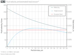
Fracturing with proppant induces erosion, and experimental evidence shows that light-weight ceramic proppants induce less erosion than natural sands. Particles with steeper features were more erosive than those with smoother, smaller surface features. Erosion increases mostly linearly with particle size (until a plateau is reached, Fig. 1), and proppants pumped in conventional assets are of a size which dramatically increases erosion in frac iron, tubing, liner, and completion equipment relative to erosion from formation sand.
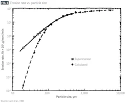
Studies modeling and measuring erosion on downhole equipment and tools during gravel pack and frac-pack operations include full-scale laboratory erosion testing of the crossover tool and attempts to calibrate numerical erosion models with laboratory test results.
For example, a crossover tool test at 15 bbl/min and 20 bbl/min optimized fracturing-tool design using a closed-loop workflow incorporating scale-model testing, numerical modeling, and full-scale erosion qualification tests. Other studies showed how to tune and validate a numerical erosion model for fracturing tools and understand crossover tool wear life during erosion.
Erosion of frac sleeves with ball seats and unlimited frac-sleeve profiles have also been studied, along with loss of zonal isolation due to erosion on these seats. Erosion was estimated from the pressure drop across each ball seat. Numerical models validated by on site experiment (~60,000 lbm of 1.7 lb/gal, 40-mesh sand pumped at 19 bbl/min) determined that 20-30° presents the proper cone angle for erosion mitigation.
A set of erosion models was developed based on the laboratory test results to simulate ball-seat erosion. The study investigated the impact of ball-seat material, cone angle, particle size, particle concentration, and particle speed. The results showed that larger proppants reduced the erosion rate of ball seats. Additional testing on an unlimited frac sleeve showed that the 45° lead-in profile reduced to 21° after pumping 10 million lbm of 100-mesh sand through the sleeve at 90 bbl/min (Fig. 2). The eroded internal sleeve profile still maintained functionality under these conditions.
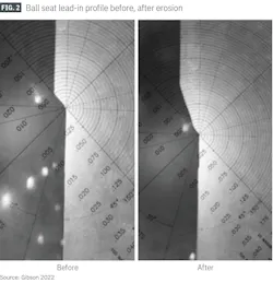
Photos of ball seats in silhouette show the erosion of the profile during the fracture job.
This study examines the erosional relationship of the hydraulic fracture design to the completion equipment based on field observations. Multi-finger caliper (MFC) and ultrasonic image logs provided post-frac erosion measurements which identified the root cause of frac sleeve opening failures. Retrieved isolation sleeves set across the upper completion components provided downhole mechanical-component erosion data.
Erosion information was collected from various wells. Fig. 3 shows a generic well diagram which captures the completion design of these wells. The lower completion consists of frac sliding sleeves and open-hole isolation packers while the upper completion consists of gas-lift mandrels with dummy valves, a wireline/coiled tubing retrievable electrical submersible pump (ESP) system, a sliding sleeve, production packer, and self-aligned muleshoe. Hydraulic fracturing used a 10,000-psi rated frac tree. Proppant consisted of 16/20 light-weight ceramic.
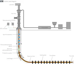
Isolation sleeve erosion
The completions incorporated two isolation (ISO) sleeves. The sleeves consist of pipes with collets and slots. One sleeve protects the ESP equipment and the other protects the sliding sleeve (SS) below the ESP.
To investigate erosion concerns, the ESP ISO sleeve was retrieved after pumping about 1.2 million lbm of proppant (in six stimulation stages) into Well A. This original ESP ISO sleeve was longer than the ESP equipment, resulting in the collet-design fishing neck in the upper section of the ESP ISO sleeve possibly allowing flow in the annulus bypass area. Fully packing the area with grease to block annular flow failed to mitigate the problem, and the collet still experienced severe erosion.
A further fishing-neck modification removed the collet and replaced it with a solid body. This alteration resolved the major erosion issue; but significant erosion still occurred on the ESP ISO sleeve. Further redesign of both the ESP ISO sleeve and the ESP including a smoother ID transition on the fishing neck adequately mitigated erosion.
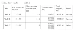
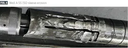
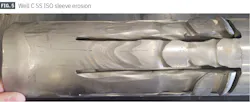
In Well A, the SS ISO sleeve also experienced significant erosion after pumping roughly 4.37 million lbm of proppant (Fig. 4), but sleeve retrieval was successful (Table 1). In Well B, the SS ISO sleeve was also retrieved successfully after pumping at an even higher pump rate. In Well C, however, the SS ISO sleeve failed, using slightly higher pump rates and proppant volume (Fig. 5). As a result, the two heel ball-actuated frac sleeves failed to open.
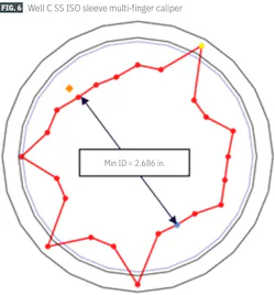
An MFC logging tool investigated the failure mechanism and data showed that the SS ISO sleeve collapsed and descended, creating a restriction which the frac balls for the last two stages could not pass (Fig. 6).
To avoid this issue for the subsequent two wells, a new SS ISO sleeve was swapped out for the old one during fracture treatment. The root cause of the erosion includes the duration of higher pumping rates, the higher proppant concentrations, and the larger total amount of proppant in Well C. The limit for any of these parameters, however, has not yet been calibrated.
A different project neglected the SS ISO sleeve. The completion schedule limited frac-pump rates to about 20 bbl/min. An ultrasonic image-logging tool deployed after the frac job in one of the wells (6.1 million lbm of 16/20 light-weight ceramic proppant at 20 bbl/min) showed no erosion across the internal profile of the sliding sleeve. This dataset led to the conclusion that high-erosion conditions result from a combination of reduced ID and larger proppant grain size, even though it was pumped at a lower pump rate.
Removal of the SS ISO sleeve may resolve the erosion issue to reduce the velocity, however, a recent design change of the upper completion to remove the SS and retrievable ESP prevented this theory from being examined further.
Ball-actuated frac sleeve
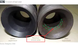
A few frac sleeves were investigated by an ultrasonic-image logging tool to confirm that they were in the open position. The study did not identify any ball-actuated frac sleeve failures due to ball seat erosion; but good zonal isolation may not have been achieved based on the location of the major erosion area identified in ball-sleeve erosion test results (Fig. 7).
Eroding the entire minimum-ID section is unlikely, thus erosion may not cause a frac sleeve shifting failure, but simulations showed that the middle ball seats (Stages #7-#15) would be expected to have internal zonal isolation failure (Fig. 8). This is because the ball seat ID increases from toe to heel and fracture treatments start from the toe. As the number of stimulation stages increases, it is assumed that more ball seats will experience zonal isolation failure.
Unlimited frac sleeve
Because of the ISO sleeves’ restrictions, there are no unlimited frac sleeves available in the market suitable for producer wells in this project. One slim-design unlimited frac sleeve was developed to increase the minimum ID of the liner for any future intervention work and reduce friction due to the ball seats.
Table 2 summarizes surface erosion fixture testing before a field trial in Well B. Based on limited observed erosion, the trial used three slim-design unlimited frac sleeves at the heel where none of the frac sleeves were shifted to the open position. Investigation, however, revealed that the profiles for sleeve shifting eroded away completely.
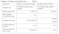
This failure highlighted the importance of performing surface erosion fixture testing under downhole operational conditions. The average fluid velocities for the surface testing and the downhole trial in Well B differed significantly: 43-48 ft/sec vs. 48-72 ft/sec, respectively. Also, the large discrepancy in fluid velocity and larger proppants pumped downhole as compared with surface tests also contributed to the failure.
Dummy valves installed in all the gas lift mandrels during the fracture treatment for the wells examined in this study showed no erosion on the main body of the valves. Erosion on the bottom dummy valve latch prompted a design change to make the dummy valves easily retrievable when later swapping to gas lift valves (Fig. 9). The materials remained the same, but a thicker design improved erosion resistance.
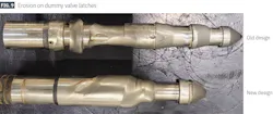
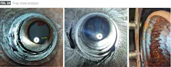
Fig. 10 shows the observed erosion on the frac tree. Erosion occurred predominantly in the swab valve and upper master-valve area. Excess erosion has not been observed in current fracture treatments, but the frac tree must be inspected and hydrotested after each frac job.
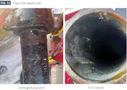
Based on a damaged pump joint (Fig. 11), the number of frac iron lines was adjusted for the designed pump rate (e.g., two lines for a pump rate higher than 32 bbl/min). Even if the pump rate is not high, high proppant concentrations and total proppant amount could each affect cumulative erosion significantly. Daily inspections of frac iron remain a crucial standard practice to avoid safety issues. The industry is currently working on standardizing frac-iron inspection.
Erosional velocity limits
Several investigators have tried to set velocity limits to prevent or minimize erosion in piping systems. A review of historical erosional velocity limits applied in the oil and gas industry indicates significant inconsistency in recommended erosional values and trends.
API RP 14E (1991) defines the erosional velocity limit by Equation 1. If solids production is expected, then a reduction in fluid velocities using c < 125 should be recommended for hydraulic fracturing. The basis and the source of API RP 14E have been the subject of speculation and, for instances in which the duration of hydraulic fracturing is limited, Eq. 1 may not be applicable to hydraulic fracturing. A limit of ve = 35 ft/sec is commonly used for frac-iron design including by the fracture service provider who performed the work in the study underlying this article.
Fig. 12 shows the erosion velocity limit dependency on c-factor for water, which is typically used as a base fluid for hydraulic fracturing. When ve = 35 ft/sec, c = 276; significantly higher than the API RP 14E recommended c-value.
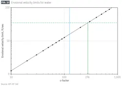
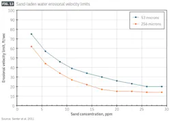
Fig. 13 shows proposed erosional velocity limits for water with straight pipes based on experimental results. The limits converge as the sand concentration becomes higher, and the limit at 29 ppm should be applicable to hydraulic fracturing because proppant concentration is higher than 29 ppm. These limits are based on the maximum allowable erosion rate of 0.001 in./yr (or 1.14×10⁻⁷ in./hr), and this criterion may be too conservative for hydraulic fracturing depending on the pumping condition (flow regime, total proppant, pumping duration, and more).
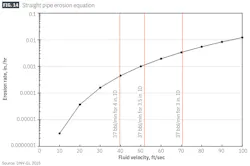
A check on the sensitivity of the downhole equipment ID on erosion uses the DNV RP501 (2015) empirical equation for a straight pipe. For simplification, a constant proppant rate is assumed. As shown in Fig. 14, an ID change from 4 in. to 3 in. impacts erosion rate via a significant velocity change. As experienced on the slim-design unlimited frac sleeve trial, the higher velocity results in erosion above acceptable limits. Special caution needs to be taken if increasing the number of stimulation stages or the overall volume of proppant.
These calculations confirm the exposure of completion equipment to severe erosion environments during hydraulic fracturing. Erosional velocity limits are dependent on the hydraulic fracturing condition (flow regime, proppant size, proppant concentrations, proppant volume, and more) and pumping duration. Determining a single erosional velocity limit for all completion equipment is unreasonable, and different erosional limits should be calculated for each piece of downhole completion equipment and for the frac iron.
Erosion qualification testing
An erosion qualification test should be performed if hydraulic fracturing is planned as a part of the equipment qualification process. It could be laboratory testing, full-scale testing, or CFD modeling. All can be performed to optimize completion equipment design.
The underlying mechanisms and components of erosion are still debatable despite years of research into friction and abrasion. Several assumptions need to be made for CFD modeling, and some input data may need to come from laboratory testing. Proppant-laden slurry flow CFD consists of complex models which can be difficult to converge on an accurate solution.
Model accuracy requires calibration, preferably backed up by full scale-testing due to the difficulty of simulating actual hydraulic fracturing in a laboratory or yard test. As shown in this study, surface-erosion fixture testing provides the best method to test completion equipment during the actual hydraulic fracturing job, but the surface condition must match downhole conditions. If possible, the internal profile should be periodically examined throughout the job to capture changes.
The opportunity to complete surface-erosion testing may be limited depending on the project, therefore a sensitivity study should be completed using a CFD model. If necessary, closed-loop design optimization may be done.
Erosion mitigation
Erosion mitigation involves multiple parameters: fluid rheology, proppant selection, proppant schedule, pump-rate reduction, and completion-equipment design change. Pump rate and proppant schedules impact the desired fracture geometry design and should not be adjusted significantly to mitigate erosion risk or the fracture geometry will be compromised.
Fluid rheology can be adjusted to mitigate erosion risk. Although a delayed cross-linker was utilized for the wells in this study, studies suggest that some improvement could be achieved by pumping an instant cross-linker or hybrid cross-linker system. An extensive cool-down pad improves erosion with these linkers by changing the fluid regime during the job.
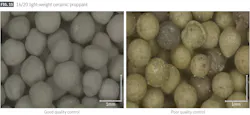
Additional mitigation can be achieved by changing proppant type. Ceramic proppant and smaller proppant have been shown to be less erosive, but proppant size can affect both fracture geometry and the resulting fracture conductivity. Good proppant quality control minimizes erosional impact while maintaining high fracture geometry. For example, the proppant shown in Fig. 15 (right) caused more erosion than the proppant in Fig. 15 (left) despite being the same type. This was confirmed after investigating the erosion on frac tree after each frac job.
Finally, completion equipment design and well design may be reconsidered when excessive erosion is still expected. This should be considered during preparation for the project and not during execution.
Frac-sleeve selection for larger jobs
Unlimited frac-sleeve systems can significantly improve project economics by increasing the number of stimulation stages per well. This will increase erosion risk, however, on all equipment that proppant passes through. It is important to check if the heel-most frac sleeve will keep functionality after pumping proppant through it. Erosion could deteriorate the differential pressure rating of the actuator after landing, resulting in the actuator passing through the target frac sleeve without opening the frac sleeve.
Ball-actuated sliding sleeve systems could be considered as an alternative to unlimited frac-sleeve systems, however, there could be a zonal isolation-failure risk as discussed. Isolation leaks can become quite severe as seen in plug failures. Also, the smaller ID restrictions increase treatment pressure due to additional friction, and milling of the ball seats could be required for future well interventions. Finally, ball-actuated sliding sleeve systems may not be an option for cemented wellbores due to incompatibility with the cement wiper plug as the number of stimulation stages increases.
As an alternative to fracture-sleeve systems, plug and perf operations can be performed in conventional reservoirs as well as unconventional reservoirs. However, the number of wells for this project is not large enough to justify 24-hr frac operations or zipper frac operations. The number of frac stages/day by plug and perf operations for this project is estimated to be 2-3, stages while 5-10 stages/day can be achieved with fracture sleeve systems depending on water availability.
Bibliography
API 14E, “Recommended Practice for Design and Installation of Offshore Production Platform Piping Systems,” fifth edition, 1991.
Clem, N.J., Hammer, A.C., O’Connell, M.M., and Amaral, A., “A Pragmatic Approach to Frac-Pack Tool Erosion Qualification Testing,” SPE-134347-MS, SPE Annual Technical Conference and Exhibition, Florence, Italy, Sept. 19-22, 2010. https://doi.org/10.2118/134347-MS
Clem, N.J., Silva, Z.S., McGuire, A.M., and Imhoff, J., “Modeling and Prediction of Frac-Pack Tool Erosion in Multi-Zone Wells,” OTC-24760-MS, Offshore Technology Conference Asia, Kuala Lumpur, Malaysia, Mar. 25-28, 2014. https://doi.org/10.4043/24760-MS
Cramer, D.D., “The Application of Limited-Entry Techniques in Massive Hydraulic Fracturing Treatments,” SPE-16189-MS, SPE Production Operations Symposium, Oklahoma City, Okla., Mar. 8-10, 1987. https://doi.org/10.2118/16189-MS
Cramer, D., Friehauf, K., Roberts, G., and Whittaker, J., “Integrating DAS, Treatment Pressure Analysis and Video-Based Perforation Imaging to Evaluate Limited Entry Treatment Effectiveness,” SPE-194334-PA, SPE Production & Operations, Vol. 35, No. 4, Nov. 2020, pp. 0730-0755. https://doi.org/10.2118/194334-PA
Davis, E.R., Constantine, J.J., White, M.L., Ferris, M.M., Watson, M.J., Schinnour, M.M., Zwarich, N.R., Woodard, M.E., Metzgar, K.N., and Nozaki, M., “A Shift or Not a Shift?” that was the Question: Robust Qualification and Testing of Available “Unlimited” Frac Sleeve Systems Yield Varied Results,” URTEC-3849448-MS, Unconventional Resources Technology Conference, Denver, Colo., June 13-15, 2023. https://doi.org/10.15530/urtec-2023-3849448
Ding, K., Yin, H., Wan, B., Cheng, H., Xiang, L., Li, J., “Analysis of Particle Size to Erosion Wear of Sliding Sleeve Ball Seat Based on FLUENT Software,” AIP Conference Proceedings Vol. 1829, No. 1, Apr. 3, 2027. https://doi.org/10.1063/1.4979756
DNVGL-RP-0501, “Recommended Practice for Managing Sand Production and Erosion,” August, 2015.
Frosell, T., McGregor, M., and Ross, C., “A Comparison of Proppant Erosion during Slurry Injection,” SPE-170793-MS, SPE Annual Technical Conference and Exhibition, Amsterdam, The Netherlands, Oct. 27-29, 2014. https://doi.org/10.2118/170793-MS
Gibson, C.M.E., “Novel Frac Sleeve Technology Designed to Replace Plug N Perf and Improve Efficiencies While Significantly Reducing Time to Production and Environmental Impact,” SPE-211006-MS, ADIPEC, Abu Dhabi, UAE, Oct. 31-Nov. 3, 2022. https://doi.org/10.2118/211006-MS
Lee, E., Russell, R., Williams, T., Carbone, F., and Clem, N., “Modeling and Prediction of Frac-Pack Tool Erosion,” SPE-166183-MS, SPE Annual Conference and Exhibition, New Orleans, La., Sept. 30-Oct. 2, 2013. https://doi.org/10.2118/166183-MS
Li, J., Hamid, S., and Oneal, D., “Prediction of Tool Erosion in Gravel-Pack and Frac-Pack Applications Using Computational Fluid Dynamics (CFD) Simulation,” OTC-17452-MS, Offshore Technology Conference, Houston, Tex., May 2-5, 2005. https://doi.org/10.4043/17452-MS
Lynn, R.S., Wong, K.K., and Clark, H.M., “On the Particle Size Effect in Slurry Erosion,” Wear Vol. 149, No. 1-2, Sept. 20, 1991, pp. 55-71. https://doi.org/10.1016/0043-1648(91)90364-Z
Mansoori, H., “Applying Higher C-Values in API RP 14E Erosion Velocity Calculations for Gas Condensate Wells - A Case Study,” NACE-2018-10627, Corrosion Conference & Expo, Phoenix, Az., Apr. 15-19, 2018.
Ramlan, A.S., Zin, R.M., Bakar, N.F.A., and Othman, N.H., “Recent Progress on Proppant Laboratory Testing Method: Characterisation, Conductivity, Transportation and Erosivity,” Article 108871, Journal of Petroleum Science and Engineering, Vol. 205, May 14, 2021. https://doi.org/10.1016/j.petrol.2021.108871
Russell, R., Nguyen, H., and Sun, K., “Choosing Better API RP 14E C Factors for Practical Oilfield Implementation,” NACE-2011-11248, Corrosion Conference & Expo, Houston, Tex., Mar. 13, 2011. https://doi.org/10.5006/C2011-11248
Salama, M.M. and Venkatesh, E.S., “Evaluation of API RP 14E Erosional Velocity Limitations for Offshore Gas Wells,” OTC-4485-MS, Offshore Technology Conference, Houston, Tex., USA, May 2-5, 1983. https://doi.org/10.4043/4485-MS
Salama, M.M., “An Alternative to API 14E Erosional Velocity Limits for Sand Laden Fluids,” OTC-8898, Offshore Technology Conference, Houston, Tex., May 4-7, 1998. https://doi.org/10.4043/8898-MS
Saldungaray, P. and Palisch, T., “Ultra-High-Strength Proppant: An Update on Deepwater Applications in the Gulf of Mexico,” SPE-189351-MS, SPE/IADC Middle East Drilling Technology Conference and Exhibition, Abu Dhabi, UAE, Jan. 29-31, 2018. https://doi.org/10.2118/189351-MS
Senters, C.W., Van Sickle, S., and Snyder, D., “Evaluation of Completion Practices in the STACK Using Completion Diagnostics and Production Analysis,” SPE-181441-MS, SPE Annual Technical Conference and Exhibition, Dubai, UAE, Sept. 26-28, 2016. https://doi.org/10.2118/181441-MS
Vincent, M.C., Miller, H.B., Milton-Tayler, D., and Kaufman, P.B., “Erosion by Proppant: A Comparison of the Erosivity of Sand and Ceramic Proppants During Slurry Injection and Flowback of Proppant,” SPE-90604-MS, SPE Annual Technical Conference and Exhibition, Houston, Tex., Sept. 26-29, 2004. https://doi.org/10.2118/90604-MS
White, M., Friehauf, K., Cramer, D., Constantine, J., Zhang, J., Schmidt, S., Long, J., Mislan, P., Spencer, J., and Meier, P., “One Stage Forward of Two Stages Back: What Are We Treating? Identification of Internal Casing Erosion during Hydraulic Fracturing—A Montney Case Study Using Ultrasonic and Fiber-Optic Diagnostics,” SPE-201734-PA, SPE Drilling & Completion. Vol. 36, No. 2, June, 2021, pp. 383-397. https://doi.org/10.2118/201734-PA
Woiceshyn, G., Dikshit, A., Agnihotri, V., Chochua, G., and Noor, M.N., “Minimizing Erosion of Downhole Proppant Flowback Control Equipment During Fracturing,” SPE-203096-MS, Abu Dhabi International Petroleum Exhibition & Conference, Virtual Event, Nov. 9-12, 2020. https://doi.org/10.2118/203096-MS
Yuan, P., Zhang, H., Huang, X., Han, J., Zhou, Q., Mezzatesta, A., and Bao, J., “Study of Proppant Erosion in Multistage Hydraulic Fracturing Using Computational Fluid Dynamics Modeling,” SPE-183819-MS, SPE Middle East Oil & Gas Show and Conference, Manama, Kingdom of Bahrain, Mar. 6-9, 2017. https://doi.org/10.2118/183819-MS
Zheng, C., Liu, Y., Wang, H., Zhu, H., Liu, Z., Cai, B., and Shen, Y., “Numerical Study on Improving the Erosion Life of Ball Seat for Oil and Gas Reservoir Fracturing,” Engineering Failure Analysis, Vol. 60, No. 1, February 2016, pp. 188-198. https://doi.org/10.1016/j.engfailanal.2015.11.050
Zou, X.-L., Guo, Y.-B., Xie, Q.-J., Wang, D.-G., and Yoon, H.C., “Numerical Study on Erosion Behavior of Sliding Sleeve Ball Seat for Hydraulic Fracturing Based on Experimental Data,” Petroleum Science, Vol. 20, No. 1, 2023, pp. 515-525. https://doi.org/10.1016/j.petsci.2022.08.037
Authors
Manabu Nozaki ([email protected]) is a completions engineer at ConocoPhillips, Anchorage, Alas. He holds a BS in resources and environmental engineering from Waseda University, Shinjuku, Japan (2006) and an MS and a PhD in petroleum engineering from Texas A&M University (2008 and 2012). He is a member of Society of Petroleum Engineers.
Nola Zwarich ([email protected]) is the wells chief engineer at ConocoPhillips, Anchorage. She holds a BS in mechanical engineering from the University of Calgary (2000). She is a member of Society of Petroleum Engineers.
Kirsty Glasheen ([email protected]) is a flowback engineer at ConocoPhillips, Anchorage. She holds a BS in petroleum engineering from University of Alaska Fairbanks (2010). She is a member of Society of Petroleum Engineers.
Madeline Woodard ([email protected]) is a completions engineer at ConocoPhillips, Anchorage. She holds a BS in mechanical engineering from Colorado School of Mines (2015). She is a member of Society of Petroleum Engineers.