Paula Dittrick
Upstream Technology Editor
Recent enhancements in relief well technology enable operators to drill into prolific reservoirs while maintaining a single relief well contingency plan. Blowout contingency planning is required by regulators in various countries and is part of many oil companies’ internal preparations.
Trendsetter Engineering Inc., a subsea engineering firm and equipment manufacturer, collaborated with Add Energy LLC (AE), a Norwegian engineering service provider, to develop the relief well injection spool (RWIS). Both firms have offices in northwest Houston. Employees of the two firms worked together to help BP PLC’s response to the Macondo well blowout and massive oil spill in the Gulf of Mexico offshore Louisiana in 2010.
The RWIS, which functions as a subsea manifold, offers a contingency for planned wells that could require a high-rate kill in the unlikely event of a blowout. The RWIS increases the flow capacity of a single relief well. In some cases, the RWIS will be an alternative to using multiple relief wells at the same time. Capping stacks are usually a faster alternative to stopping a blowout, but in some cases a relief well followed by a dynamic kill may be the only option to bring the well under control.
The RWIS was designed using components common in deepwater operations, including conventional wellhead connectors. AE evaluated the concept for a kill spool during 2014 while Trendsetter designed the spool.
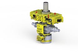
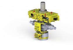
Trendsetter and AE received a US patent on May 15, 2018, for the RWIS (Fig. 1) and method for killing a blowing wellbore.
Operators needing to kill a blowout can increase the relief well pumping capacity by placing an RWIS between the relief wellhead and the BOP to inject kill fluids (Fig. 1). Photo from Trendsetter, Add Energy.
Brett Morry, Trendsetter global technical director, said, “We just repackaged existing components. We built this on spec…Industry has responded. The RWIS was validated by industry by multiple contracts.”
Operators in the Barents Sea, North Sea, and other offshore locations have signed contracts for licenses to ensure access to RWIS. In some cases, the certificate of RWIS access is included in the operator’s application submitted to regulators for drilling permits.
Access subscriptions to RWIS are issued per well and are in effect for 1 year from the spud date.
The RWIS can be deployed rapidly by air, ground, and marine freight anywhere worldwide. One assembled unit is stored near the Bush Intercontinental Airport in Houston. A second unit is available that could be assembled quickly if needed.
Morry said government rules for many countries require operators have a feasible blowout contingency plan in case of a worst-case scenario before issuing a drilling permit. Norway’s Petroleum Safety Authority calls for a single relief well contingency plan. US regulators require a relief well plan, but do not specify how many relief wells.
Relief wells have been drilled since the 1930s. Morry said today’s dynamic kill methods involve frictional forces caused by mud pumped into the blowing well to increase the pressure in the wellbore and stop flow from the reservoir.
Ray Tommy Oskarsen, AE senior vice-president of well control and blowout support, said industry guidelines advise against planning wells that would require multiple relief wells.
The offshore industry never has drilled two relief wells that simultaneously intersected an offshore blowout. The only case of two simultaneous relief wells intersecting a blowout involved an onshore well in El Isba, Syria, during 1995.
RWIS logistics
Oskarsen said the RWIS may offer a less complicated and more efficient alternative to drilling more than one relief well, assuming intervention is the only option. When multiple relief wells are drilled, appropriate rigs must be procured, drilling from appropriate surface locations, and several wells must be hydraulically connected with the blowing wellbore followed by a simultaneous coordinated kill operation.
Drilling crews must ensure the relief well intersects the blowout in the correct position and fluid pumping operations are effective. Numerous potential technical complications exist when drilling a relief well, including:
• High gas-oil (GOR) ratio and discharge rates.
• High-pressure reservoirs.
• Big boreholes and long open-hole sections.
• Long choke and kill lines on deepwater relief wells.
• Narrow windows between pore and fracture pressures.
• Shallow reservoirs with limited ability to build friction and hydrostatic pressure.
• Complicated flow scenarios including multiple reservoirs, crossflows, partial broaches, and annulus communication.
• Remote areas with limited equipment available for pumping operations.
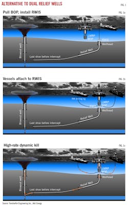
The RWIS is designed to be installed on a relief well beneath the blowout preventer (BOP) to provide additional inlets or flow connections for pumping kill mud into the out-of-control wellbore (Fig. 2a-2c).
Each inlet is equipped with dual fail-safe barrier valves to provide the necessary pressure containment in the relief well. The RWIS is designed to pump up to 200 bbl/min of kill mud through one relief well as opposed to the conventional method of drilling multiple relief wells.
During the kill operation, dual high-pressure flexible flowlines connect pumping units from separate vessels positioned near the relief well drilling rig to the RWIS inlets.
The erosion-resistant RWIS, rated to 10,000 ft of water and 15,000 psi, is designed to American Petroleum Institute specifications. It’s configurable with or without a shear ram. Hydraulic modeling using AE’s Olga-Well-Kill simulator validated the RWIS in hypothetical case studies for shallow and deepwater wells.
In an RWIS base case simulation, engineers calculated 40 bbl/min pumped from the relief well down the annulus, 20 bbl/min pumped from the relief well rig down drill pipe, and 70 bbl/min pumped from each of two support boats or drilling rigs.
A shallow-water blowout simulation was run for 1,214 ft of water with a 10 ppg (1.2-specific gravity, sp gr) mud weight for a reservoir at 4,265 ft TVD and a relief well kill point at 4,232 ft TVD. The study called for 12.5-ppg (1.5-sp gr) kill mud, 4-in. choke and kill (C&K) lines and 5-in. flex lines. A 9 5/8-in. casing was set in the relief well before the intersect. Pumping requirements on each support vessel must not exceed 7,250 psi and 11,500 hp.
The maximum achievable combined kill rate was 130 bbl/min. But a maximum kill rate of 200 bbl/min can be achieved using 4.5-in. C&K lines, 6-in. flex lines, and 14-in. casing with a 1,000 ft., 9 5/8-in. liner in the relief well.
A deepwater blowout simulation was run for 4,920 ft. of water with a 10.4-ppi (1.25-sp gr) mud weight for a reservoir at 18,045 ft TVD, figuring a relief well kill point at 17,880 ft TVD.
The study called for 14.6-ppi (1.75-sp gr) kill mud, 4-in. C&K lines and 5-in. flex lines. A 9 5/8-in. casing was set in the relief well before the intersect. Pumping requirements on each support vessel must not exceed 7,250 psi and 11,500 hp. Maximum achievable kill rate was 90 bbl/min.
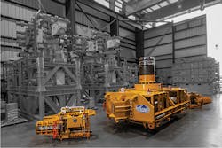
But a maximum kill rate of 200 bbl/min can be achieved using 4.5-in C&K lines, 6-in. flex lines, and a 14-in. casing with a 1,000 ft, 9 5/8-in. liner in the relief well. Fig. 3 shows the large-bore stabs used to connect the RWIS to flexible lines.
Equipment manufacturer Trendsetter Engineering Inc. tests the RWIS at its plant in northeast Houston. The RWIS (center) includes two 4-in. large bore flowline hotstabs (left, right) to connect with flexible lines and receive kill mud if a relief well needs to be drilled (Fig. 3). Photo from Trendsetter, Add Energy.
The RWIS increases build height and distance to the flex joint. Analysis shows a fatigue life of 30% of the fatigue life of the wellhead without the RWIS.
New wellheads are designed to last for more than 500 days of drilling. If needed, the RWIS is expected to be used for about 7 days. Wellhead fatigue can be mitigated using a tethered BOP, which arrests movement of a BOP stack and restricts lateral offset during a drift-off event.
The RWIS has a 20-year shelf life and a 1-year subsea life. Trendsetter tests the RWIS once yearly.
Post-Macondo drilling
After the Macondo blowout, development of surface intervention methods and subsea capping systems received much industry attention. Operators recognize relief well drilling and a dynamic kill operation will, in many cases, be the safest and most likely successful well intervention.
BP and its partners drilled two relief wells for Macondo but only one intersected the target while the second served as a backup.
For Macondo, crews on Transocean Ltd.’s Development Driller III semisubmersible intercepted the annulus of the deepwater incident well with a relief well on Sept. 16, 2010. Total measured depth for the annulus intercept point was 17,977 ft. A dynamic kill was not needed on Macondo because a bullheading operation followed by cement using a surface intervention was executed before the intersect.
An estimated 4.9 million bbl leaked from the well, of which BP estimates it captured 800,000 bbl. BP operated the well on Mississippi Canyon Block 252 off Louisiana. Since then, US offshore regulatory agencies were restructured and some deepwater drilling rules revised.
Operators must demonstrate the feasibility of potential relief well operations, including trajectories, to obtain a deepwater drilling permit in the US gulf.
BP’s internal best practices require verification of at least two relief well potential locations for a deepwater well.1
Before the revised US rules, few operators had created formal relief well plans. Given post-Macondo, operators sought a way to plan relief wells without having to generate intercept plans for every casing section.
BP developed a systematic contingency relief well planning process in-house, emphasizing the need for repeatable methodology and specialized engineering tools.
This process involves using a dynamic kill simulator to determine if the exposed formation fracture gradient at these points has the required strength to circulate out the volume and intensity of the hydrocarbon flow, bringing the well under control.
BP uses commercially available software for its relief well designs, saying the technology provides optimal results in minutes and allows a multidisciplinary collaborative team to analyze more options and cases faster. The software calculates possible drillable relief wells while acknowledging surface and subsurface constraints.
The offshore Wheatstone LNG project in Western Australia uses subsea big-bore gas wells. The highly productive wells represent a gas source, that if accidently allowed to flow unhindered, could result in a difficult well-control situation.
Chevron Australia’s Wheatstone drilling and completion teams evaluated various options for relief well responses that might be necessary in case of a blowout. The analysis indicated three or four relief wells would be required simultaneously. Based on these results, both the well and the drilling plans were redesigned to minimize the number of required relief wells to two.2
References
1. Goobie, R., Allen, W., Lasley, B., Corser, K., and Perez, J., “A Guide to Relief Well Trajectory Design using Multidisciplinary Collaborative Well Planning Technology,” Society of Petroleum Engineers/International Association of Drilling Contractors Drilling Conference and Exhibition, London, Mar. 17-19, 2015.
2. Upchurch, E., Falkner, S., House, A., Nguyen, C., and Russell, K., “Blowout Prevention and Relief-Well Planning for the Wheatstone Big-Bore Gas Well Project,” SPE Technical Conference and Exhibition, Houston, Sept. 28-30, 2015.
About the Author
Paula Dittrick
Senior Staff Writer
Paula Dittrick has covered oil and gas from Houston for more than 20 years. Starting in May 2007, she developed a health, safety, and environment beat for Oil & Gas Journal. Dittrick is familiar with the industry’s financial aspects. She also monitors issues associated with carbon sequestration and renewable energy.
Dittrick joined OGJ in February 2001. Previously, she worked for Dow Jones and United Press International. She began writing about oil and gas as UPI’s West Texas bureau chief during the 1980s. She earned a Bachelor’s of Science degree in journalism from the University of Nebraska in 1974.


