Understanding process heat transfer

Norman P. Lieberman
Process Improvement Engineering
Metairie, La.
One key to becoming a good process engineer or effective operator is understanding heat transfer. The 10 most common heat-transfer malfunctions are:
• Internal bypassing.
• Vapor binding.
• Flux limits on reboilers.
• Low-velocity sensible heat transfer.
• Condensate backup.
• Blowing the condensate seal.
• Vapor lock.
• Low Reynolds number on tube-side sensible heat transfer.
• Effect of surface roughness.
• Excessive heat flux in fired heaters.

Internal bypassing
At an asphalt plant in Alabama, my client could not meet the asphalt-paving grade penetration specification because of a poorly performing vacuum condenser. I measured the water flow with an ultrasonic flow meter, calculated the tube-side water pressure drop (DP), and compared it to my field-measured DP. My calculated DP was four times greater than my measured DP, confirming my worst fear. We found a leak between the channel-head pass partition baffle and channel-head tube sheet (Fig. 1).
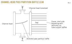
Half of the cooling water was bypassing the tubes (DP ≈ V2).
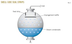
On the shell side, the usual cause of bypassing is the maintenance guys having discarded the shell-side seal strips, which in their minds, serve no process function. But they do: they retard internal bypassing across the top of the tube bundle in the gap created by the shell-side impingement plate (Fig. 2).
Let’s say I have an exchanger with a center baffle in the channel head (Fig. 1). Note that there is a gap in the center of the tube bundle between the tubes. What’s going to prevent the shell-side liquid from flowing through this gap? If the shell side baffles are cut horizontally, there’s no problem. If baffles are cut vertically, however, the shell-side flow can bypass the tubes through this gap.
Luckily, there is a standard solution to this problem. It’s called dummy tubes. These block off the bypass area. They’re inserted in the tube bundle but aren’t attached to either the channel-head or floating-head tube sheets.
To stop bypassing around the periphery of the bundle, I use seal strips inserted into slots cut into the tube-support baffles (Fig. 2).
Vapor binding
I’m often amazed as to how venting a little air from beneath the channel head of a steam condenser dramatically increases reboiler duty.
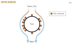
All noncondensables—whether CO2, hydrocarbon gas, or hydrogen—have the same effect. I call it vapor binding. This occurs when steam condensate runs out of the tubes and condensable vapors accumulate, surrounding the condensing surface with a temporary fouling layer and shielding the tube-surface area from contact with the steam, just like any permanent fouling deposit (Fig. 3). A tiny amount of continuous venting of noncondensables prevents this problem.
I once encountered a small leak of propane in a propylene-propane splitter that reduced reboiler duty by half at a plant in Texas City, Tex. I corrected this by opening a vent beneath the channel-head pass partition baffle.
A more common problem to watch out for, however, is CO2 evolved in steam boilers when carbonates in the boiler-feed water break down.
Flux limits on reboilers
I once worked on a reboiler used in a propane-propylene splitter. It was working okay, but it was old. Since about 15% of the tubes had been plugged over the last 20 years, I decided to purchase a new tube bundle identical to the existing bundle. When I put the reboiler back into service, I was limited to 50% of the reboiler’s former capacity, which came as a nasty surprise.
At the time, the reboiler used 30 psig steam. Thinking that hotter steam would transfer more heat, I tried using 100 psig, which I had connected to the reboiler at considerable expense. This only made the problem worse.
Dick Nutt, an older engineer, explained the problem to me.
“Norm, get a new frying pan. Real smooth. Get it real hot. Now, gently drop a tablespoon of water on the hot pan. It ain’t gonna boil away like you might think. The layer of steam that’s vaporized from the water doesn’t let the water touch the pan. If you want the water to boil away fast, shut off the burner and let the pan cool off some. Go home and try it.”
So I did, but the water flashed off from the pan immediately.
“Dick,” I said the next morning, “it didn’t work like you predicted. The water boiled off right away.”
“Did you use an old pan or a new pan?”
“I don’t have any new pans. I used one my grandma gave me, and I guess it’s kinda rough and scratched.”
“It’s the same with your reboiler. The smooth surface doesn’t have any nucleate boiling sites where boiling can be initiated,” Dick explained.
“Oh, yeah,” I said. “Like in high school chemistry lab, when we used those boiling stones. But what should I do about my propane reboiler?”
“Norm, put the old bundle back in.”
“I’m surely not gonna do that!” I said.
“Have the bundle coated with Linde high-flux tubing,” Dick suggested.
“That sounds kind of expensive, Dick.”
“Okay, Lieberman, then just have the exterior of the tubes sandblasted until they have a rough surface like the old tube bundle.”
I followed Dick’s recommendation, and it worked like a charm.
Low-velocity sensible heat transfer
You read about this stuff in school, but it probably didn’t mean too much. For example, a low Reynolds number creates high-film resistance to heat transfer due to laminar flow. Reynolds number = (V × density × tube diameter) ÷ viscosity, where V = velocity.
When the Reynolds number falls below 2,100, heat-transfer efficiency is supposed to fall quickly due to laminar flow. I learned about this at the Good Hope refinery in Louisiana. We had designed a heavy fuel oil cooler with water on the shell side and high-viscosity fuel oil in the tubes, and it didn’t work. The fuel-oil product was running down to our product tank at 250° F. We blew the roof off the tank when the water heel in the bottom of the tank boiled. The roof sailed across St. Charles Parish and landed in someone’s backyard.
After this happened, I switched the fuel oil onto the shell side and put the cooling water in the tubes. The heat transfer coefficient increased by a factor of three.
Why? Vortex shedding. The velocity of the fuel oil was still low and its viscosity was still very high. You can see this in New Orleans as the Mississippi River flows past the French Quarter. The water flows across the old dock pilings, creating swirls and turbulence. As long as the cross-flow velocity passing perpendicularly past tubes exceeds 3 fps, the laminar film heat-transfer resistance is destroyed.
I have told this story 800 times in my seminars since 1983 as proof that our technical education does prove helpful every once in a while.
Condensation, condensate backup
When a pound of steam condenses at atmospheric pressure and 212° F., 1,000 btu are released. When the resulting condensate cools to 112° F. from 212° F., 100 btu are released. Subcooling condensate does not release much heat. Also, it’s about 10 times more difficult to transfer heat to a metal surface from a liquid than from a condensing vapor.
I can likely transfer 100 times more heat by contacting steam against a metal surface than by contacting that metal surface with stagnant hot water. In a heat exchanger, those tubes that are covered by steam condensate are doing very little, or nothing, to heat up the fluid on the tube side. This problem of condensate backup is equally valid for condensing propane and butane as it is for steam.
My mother was familiar with this problem when the radiator in our old apartment house in New York would get cold. Mom would bang on the condensate drain line with a hammer.
“Mom,” I would ask, “why are you doing that?”
And Mom would say, “I’m trying to bring up the heat.”
I suppose she meant to say, “I’m trying to dislodge the hardness deposits from the condensate drain line to expose more of the radiator’s surface area to steam, and retard condensate backup, which is reducing the surface area of the radiator exposed to steam.”
Operators react to condensate backup by draining the condensate to the sewer, which accounts for much of the poor condensate recovery in most process plants.
Blowing the condensate seal
When I was 19, I used to worry a lot about girlfriend problems—either not having a girlfriend or having multiple girlfriends simultaneously. It’s the same with condensate backup. Too much condensate backup wastes heat-transfer surface area, while no condensate backup causes steam to blow through the steam-side outlet.
The steam trap is intended to prevent this. The trap will open to allow water to pass but closes to prevent steam from blowing through it. When steam blows through the outlet nozzle, operators say, “We’ve blown the condensate seal,” and reboiler duty will suddenly drop by about half, even though steam flow to the reboiler hasn’t diminished.
I don’t know why this happens. I suspect that whereas high velocity promotes good, sensible heat transfer, it also retards heat transfer from a condensing vapor onto a metal surface.
If I encounter a reboiler that is performing poorly, I will conduct the following test:
• Monitor the reboiler-process outlet temperature.
• Partially close the steam-condensate outlet valve.
• If the process outlet gets hotter, then I’ve stopped blowing the condensate seal, which is good.
• If the process outlet gets colder, I’ve been suffering from condensate backup and need to increase the condensate (water) flow from my reboiler.
Incidentally, steam traps aren’t reliable. It’s better to use a condensate pot and pump the condensate out of the pot through the pot’s level-control valve.
Most often, plant operators manually drain condensate to the sewer at a rate that maximizes reboiler duty. The purpose of the condensate pot and pump is to prevent loss of valuable steam condensate to the sewer.
Vapor lock
I grow smarter by learning from my mistakes. For example, in my earlier years, I would design for condensate from a 150-psig steam reboiler to drain through a 4-in., 500-ft long condensate pipe into a condensate flash drum that operated at 10 psig. The operators would then find it necessary to drain the condensate to the ditch.
As condensate flowed through the 4-in. pipe, it experienced a small pressure drop. The reduction in pressure caused the condensate to flash or partially vaporize. The density of the evolved steam is about 0.25 lb/cu ft. The density of hot water is 60 lb/cu ft. Therefore, 1 cu ft of water flashing to steam expands 240 cu ft. This chokes off the flow and pushes up the condensate level in the reboiler, greatly reducing heat-transfer rates.
Operators avoid the problem by diverting the condensate to the ditch. Having learned from my experience, I now pump—rather than pressure-out—the condensate to the flash drum.
Tube-side sensible heat transfer
I like to keep the tube-side flowing velocity high. Anything less than 3 fps is too low. I design for 6-10 fps for two reasons: To stay away from laminar flow due to a low Reynolds number (caused by high viscosity and low velocity) and fouling.
If viscosity is less than 4-8 cp or cst, I don’t worry about it. But for cool crude oil from Venezuela, where viscosity can be 40-80 cp, I worry about laminar flow, not because I have read about the problem but based on my own experience. High velocity will offset high viscosity.
One problem with high velocity is that DP varies in proportion to V2 × L, where DP = pressure drop, V = velocity, and L = flow-path length.
Any velocity much above 12 fps will promote erosion. Converting an existing tube bundle from two tube-side passes to four passes will double velocity, which is good. But DP will increase by a factor of eight, or DP = (2)2 × 2.
Tube roughness
Which is best for heat transfer? A super-smooth, stainless-steel tube or a rough, pitted carbon-steel tube?
I used to worry about this a lot when I worked for American Oil’s El Dorado, Ark., refinery in the 1960s. Now I realize it depends on the circumstances. If you are vaporizing freon or boiling clean propane (i.e., pure latent heat transfer), then to avoid a flux limitation (12,000 btu/hr/sq ft), a rough, pitted surface, which can permit heat flux exceeding 20,000 btu/hr/sq ft, is best. I learned this at El Dorado in 1967 on a propane refrigeration loop.
If fouling is the predominant heat-transfer resistance, then smooth, shiny, 316 stainless steel (SS) is the best choice. We retubed our FCC tube bundles in American Oil’s Whiting, Ind., refinery with stainless to replace carbon steel and maintained excellent heat-transfer coefficients. But that was all heat transfer between liquid, not for our reboilers.
Incidentally, don’t put 316 SS tubes in contact with carbon-steel tube support baffles as I saw at the Coastal Aruba Refining Co.’s Aruba refinery. Galvanic corrosion will destroy the baffles.
Fired-heater excessive tube flux
Radiant heat transfer is a very powerful force. The sun is 60 million miles away from us and still heats up New Orleans. In the firebox of our heaters, we have mainly radiant heat transfer. For high-chrome tubes, a low-heat transfer flux rate is 8,000 btu/hr/sq ft of external tube.
For 12-14% (i.e., high) chrome tubes, a high-heat transfer flux rate is 16,000 btu/hr/sq ft. Ever since I melted the tubes at the Texas City refinery’s spent-sulfuric acid decomposition furnace in November 1974, when we lost flow but kept the burners firing, I worry about furnace tubes melting.