Large ethylene plants present unique design, construction challenges
The design and manufacture of equipment in ethane crackers with more than 1 million tonnes/year (tpy) of ethylene production create many problems during engineering, procurement, construction, and start-up. Current technology constraints due to the exclusive use of centrifugal compressors limit ethane cracker capacity to 1.4 million tpy of ethylene in a single compression line.
Other considerations, however—such as suitable location, feedstock availability, downstream unit reliability, turndown ratio requirements, consequences of furnace and plant outages—will take precedence over the design and construction problems when investors determine the capacity of new plants.
As with other baseload plants (LNG, gas-to-liquids, ammonia, methanol, and methane-to-olefins), the race for larger single-train plants will not stop due to these considerations.
Technip Group is already working on the design and procurement possibilities of the first 2 million-tpy ethane cracker, single-compression line, using proven centrifugal machines and new furnaces.
This article covers the design considerations of the 1 million tpy and larger, "mega" ethane crackers.
The data and subsequent interpretation in this article are based on actual, in-house projects of 1.0 million tpy (Pars Petrochemical Co.), 1.3 million tpy (confidential), and 1.4 million tpy (Jam Petrochemical Co.) at various stages of progress.
Increased demand
The capacity and throughput of steam crackers are continuously growing due to the ever-increasing world demand for polymers (polyethylene and polypropylene in particular) and other olefin-based derivatives.
Basic olefins like ethylene and propylene are now considered commodities. Similar to electricity or cooling water, basic olefins must be produced at the lowest cost, continuously, and reliably to feed the now-integrated downstream units, which are the real profit centers.
The fact that the ethylene specification from steam crackers has changed very little over the past 35 years reinforces the commodity concept. The worldwide purity specification is set at 99.9+%, and ethylene's derivative products have evolved drastically into more-sophisticated formulas. Most grades of polyethylene did not even exist 20 years ago.
Product selection, return on investment
During the past 40 years, the capacity of a typical single-train steam cracker has increased tenfold, to 1-1.4 million tpy in 2000 (e.g., Jam Petrochemical's plant in Assaluyeh, Iran) from 100,000-140,000 tpy in the early 1960s.
In terms of return on investment, one must consider an integrated complex that consists of a steam cracker, polyolefins units, and often other derivatives, with supporting facilities. The budget for a 1-million-tpy grassroots olefins complex is much more than $1 billion.
The financing strategy is always crucial when planning these capital-intensive projects. Owners have historically applied these methods to optimize capital spending:
- Deferred capital: postponing the installation of major equipment required to reach final capacity. In practice, cracking furnaces, compressors, and heat exchangers are candidates. Owners can consider this method when the final capacity is required in about a 2-year span.
- Duplicate plant. This strategy was popular in the 1970s in a rapidly growing market. The staging of large investment budgets, prudent market expectations, and owners' reluctance to scale-up a known technology to an excessive capacity were rationales for this method.
- Double compressor line and large, expandable furnaces. This method was used when the first 600,000-tpy plants were built in the 1970s. Reliability considerations were the main reasons for this approach.
Financial costs are currently lower, which makes staged investment less attractive. The market is well developed and more predictable, reducing the risks related to a capacity decision.
More-accurate design data, tools, and software, coupled with more-stringent lump-sum, turnkey contracts, create a lower possibility of built-in capacity expansions compared to older designs.
Assuming there is sufficiently available feedstock, the best strategy is to select the largest single-train capacity required for a market forecast of 10 years, with enough feedstock available at attractive cost. This latter consideration is most often decisive, considering that final (polymer) product transportation can cover a large geographical zone at relatively low cost.
Site selection
Current investment projects consider new capacity in the 1.5-2.0 million-tpy range. The continuous availability and long-term cost of feedstock for these mega crackers are the prime determinants for plant location and capacity.
The challenge depends to some extent on the nature of the feedstock. Ethane is preferred due to a minimum investment per tonne of ethylene and nearly no by-products. Liquid feeds like naphtha require a more-complex separation process, but also provide additional valuable by-products, such as propylene, butadiene, and aromatics.

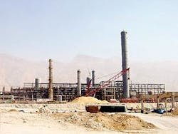
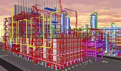
The largest crackers currently under construction, the Jam 1.4-million-tpy ethylene plant (Fig. 1) and the Pars 1-million-tpy plant, are both located in Assaluyeh, Iran.
The Jam cracker is a dual gas and liquid cracker, while Pars is an ethane-only cracker.
Assaluyeh constitutes an appropriate site for large complexes. Because it is close to offshore gas fields, plants there receive an abundant, durable, and economic feedstock. And because it is on the seaside, it offers a suitable offloading arrangement necessary to handle the ultra-large equipment and the massive amount of bulk materials required for constructing these plants, as well as the loading docks for the shipping of end products.
Assaluyeh also provides easy access to the large amount of cooling water required for both petrochemical complexes through dedicated seawater intake channels.
Final capacity, turndown ratio
The owner must select the optimum cracker capacity after determining the product slate, site, and feedstock.
At this point in the design process, the mechanical constraints of some of the key elements (cracking furnaces, compressors, vessels, piping) of these mega plants become a limitation. The availability of proven equipment and the reliability of larger items now becomes a decision factor, when one considers the capacity target.
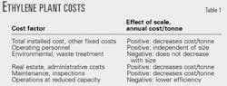
Table 1 shows key factors that must be considered to assess the economy of scale; each has a major effect on the cost per tonne of ethylene.
When plant capacity increases, these factors indicate a global decrease in cost per tonne of olefins produced:
- The number of operating personnel does not vary much with plant size. Plants are all automated to a point where the number of shift personnel remains the same, regardless of throughput.
- Environmental considerations and waste treatment are definitely more stringent, and their implementation costs are the only ones that actually increase in absolute values, and hence, in costs per tonne of product.
- The other costs (real estate, administration and maintenance, financial, etc.) are less sensitive to size.
- At reduced throughput though, the lower global efficiency of the mega cracker may significantly increase its operating costs.
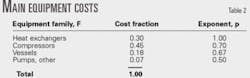
Table 2 shows the main equipment cost breakdown for a typical naphtha cracker of 600,000-800,000 tpy, excluding furnaces.
Assuming that each group of equipment follows a "power law" for investment cost vs. capacity, it is possible to devise a relationship for new mega-plants:
I/Io = (C/Co)p
where:
I = Investment cost for family F, $.
Io = Known investment cost for an operating naphtha cracker, $.
C = Capacity, tpy.
Co = Known capacity of an operating naphtha cracker, tpy.
p = Power factor for family F, dimensionless.
The total installed cost (TIC) per tonne of ethylene decreases with an increase in plant production; the exponential factor of investment vs. capacity applies here (p = 0.77-0.80). This is slightly higher than the usual value of 0.66-0.70 for petrochemical plants due to the effect of compressors and heat exchangers (Table 2).
Given a base cost of 100/ tonne of ethylene for a 700,000-tpy plant means that doubling the capacity to 1.4-million-tpy reduces this base cost to 85/tonne of ethylene.
Equipment sizes
Many single-train ethylene plants with capacities of 800,000-1 million tpy have operated for several years with proven track records.
In the 1980s, the large crackers of 600,000 tpy were usually designed with 8-10 furnaces, each producing 75,000-80,000 tpy of ethylene.
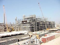
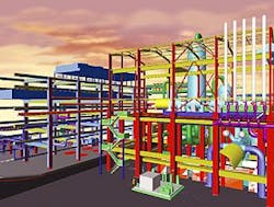
Jam Petrochemical's cracker (Fig. 2) also has 10 furnaces (five plus one spare on gas, four on liquid) and its capacity is more than twice the former large crackers of the '80s; it delivers more than 170 tonne/hr of ethylene. Each heater is designed to produce 150,000-160 000 tpy of ethylene (Fig. 3).
At these flow rates, the designer faces many design challenges.
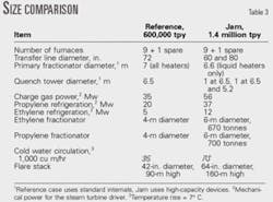
Table 3 shows a few size comparisons between a reference plant of 600,000 tpy and Jam's current 1.4-million-tpy plant, both based on the same gas and liquid feedstocks.
All these large items impose unusually large spacing due to their sheer dimensions and subsequent construction and maintenance requirements: the plot plan covers an area of nearly 320 x 270 m.
Cranes and lifting devices are required for 1,300-tonne lifts of tall vessels. This requires additional free space, aboveground and underground, to allow for their turning radius and ground resistance.
Underground networks for cooling water, fire water, and drainage systems are so bulky with huge trenches, that electric and instrumentation cables are located in aerial ducts to save space and erection time.
The electrical system (voltage levels and switchboards) is also designed and sized to cope with a power demand that exceeds what is usually required in smaller plants.
Safety systems use normal design methods to cope with the extraordinary capacity factor: hold-up times are not minimized, block isolation valves are provided as with other designs, flare load-limiting devices are also implemented as is now the case for almost all designs.
The Pars plant control system features the use of Smart and Fieldbus technologies, based on tree topology. The global safety protection is performed through a dedicated high-reliability, quadruple modular redundant system.
Equipment supplies
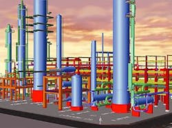
The rationale behind mega-cracker designs is for the plant to operate with a single compressor train for the charge gas and the propylene refrigeration services, which uses proven elements for the casing, rotors, and all ancillary elements (Fig. 4).
The charge-gas machine is the most critical as far as suction volumetric flows are concerned. We therefore decided to set the pressure profiles in such a way that the centrifugal compressor inlet flow is limited to a maximum proven value of nearly 300,000 cu m/hr, which derives from the present manufacturing limitation for the wheels.
This represents an acceptable compromise between the desired cracking yields and proven capabilities of rotating machines, while maintaining decent on-stream factors.
A few major worldwide suppliers can propose proven and efficient machines for this service.
A new option is to use axial compressors, such as those installed in LNG plants, which could possibly remove this particular bottleneck.
Other rotating equipment, which are much larger and more powerful than required in a standard ethylene plant, remain within the proven ranges of operations in similar services.
The vessels create other interesting design challenges: Some of them are so large in diameter that the standard flow distribution criteria do not apply. Their design imposes new calculation tools in the field of computerized fluid dynamics, both for the vessels and the ultra-large piping (Fig. 5).
Fluid distribution and behavior do not follow the standard criteria for trays and packing, and require new approaches and solutions.
Length-to-diameter ratios for certain beds are getting close to 1 (as wide as they are tall). The diameters of major columns, however, have not increased that much compared to the designs 20 years ago.
Vendors have made major improvements in fractionation systems, including high capacity, high-efficiency devices now on the market, and have proven them in operations.
Piping sizes are such that almost every line is critical and needs to be stress calculated to check its routing, and to define its supporting and controlling loads on equipment flanges. Also, if the plant is located in a high-seismic area, considerations of additional constraints and dynamic forces of seismic origin must be included in these stress calculations.
The piping layout for sizes of 60+ in. imposes new stress criteria and support devices because the flexibility constraints have a large impact on space and overall plot requirements.
The associated fittings and valves as well as flanges greater than 60 in. are not all covered by the standard ASME codes and sometimes are simply not available in the desired dimensions on the market.
Effect of scale
Table 4 summarizes our conclusions for installed equipment. Some of the more important conclusions are:
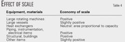
- Large machinery. Reliability and spare parts are nearly independent of scale.
- Large pressure vessels. Inspection costs are independent of scale.
- Heat exchangers. Shell and tubes often come in multiple units and installed area is proportional to capacity. There is no economy of scale.
- Bulk materials. Sizable economy of scale.
Operating costs
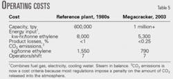
Table 5 shows that the effect of scale, when combined with technology improvements (burners, fractionation devices, metallurgies, control systems, etc.), gives the owner significant cost savings.
Acknowledgment
The authors thank Dr. Victor Kaiser, Technip Ethylene Business Unit technology advisor, for his decisive input and valuable contribution.

The authors
Michel H. Buffenoir is chief executive officer of the ethylene business unit for Technip Group, Paris, having joined Technip in 1995. During his 35-year career, he has held the positions of process engineer and executive project director of large projects. His experience covers project management, front-end engineering design development, contract negotiation, and construction supervision for the oil and gas, chemical, petrochemical, pharmaceutical, and energy-related industries. Buffenoir holds an MSc in chemical engineering from the Ecole Nationale Supérieure de Chimie, Lille, France.

Jean-Marc Aubry is the project director for Technip Group, Paris. Currently, he is in charge of the 9th Olefin Complex, ethane cracker for Jam Petrochemical Co., Assaluyeh, Iran. Aubry started at Technip in 1980 as a process engineer in gas treatment. He has experience in process, field, and project work for major projects such as gas treatment, fertilizers, polymers plants, and ethylene crackers. Aubry holds a degree in chemical engineering from the University of Technology of Compiegne, France.

Xavier Hurstel is deputy project director and engineering manager for Technip Group, currently assigned to the 10th Olefin Complex, cracking plant project, Assaluyeh, Iran. He has worked for Technip since 1975, first as a process engineer in the ethylene technology process group and then as project manager for both refining and ethylene projects. He holds an MSc in chemical engineering from Institut National Supérieur de Chimie Industrielle de Rouen, France.