LIQUIDS ENTRAINMENT—2: On line liquid-entrainment testing confirms CFD model prediction
This is the second of three articles that describes BP’s experience with reciprocating compressor damage from liquids intrusion at two facilities, in Oklahoma and Alaska.
Part 1 of the series (OGJ, May 18, 2009, p. 46) discussed the role of changing operating conditions in leading to compressor damage and reviewed details of the Oklahoma incident.
This second article reviews the validation of CFD modeling by on line laser isokinetic probe sampling for liquid entrainment and the impact of NGL solubility in compressor lube oil.
The concluding article (OGJ, June 8, 2009) will examine the use of state-of-the-art in-line cyclonic separation technology to mitigate liquid entrainment.
BP owns and operates the Milne Point oil production facility on Alaska’s North Slope where processing facilities are enclosed in heated, adjoining modules. The gas compression module houses two 3,450-hp reciprocating compressors.
Over time, the frequency and severity of compressor component failures increased. Intense examination identified both mechanical and process-related causes for the failures, including entrainment of water and NGLs in the compressor suction.
Damage caused or exacerbated by ingested liquids included bearing failures, damaged cylinder lining, sheared wrist pins, sheared cylinder attachment bolts, and cracked pistons.
At Milne Point, poor separation performance of existing suction scrubbers was predicted by computational fluid dynamics (CFD) modeling and confirmed by laser isokinetic probe sampling to quantify liquid entrainment. Analysis of operating data also indicated condensation of liquids in suction piping downstream of the scrubbers.
A process flow diagram for the Milne Point compression facility appeared in Part 1 and identifies the equipment tags and cylinder numbering sequence referred to in this second article and in the concluding article (OGJ, June 8, 2009).
Liquid source
The suction bottles on the Nos. 1 and 2 cylinders are immediately downstream of the suction scrubbers. The presence of water and NGL in these bottles clearly indicates that the source of these liquids is either scrubber liquid carryover, condensation in uninsulated suction piping and pulsation bottles, or a combination. Process analysis and operating data confirmed that both mechanisms contribute to the presence of condensate and water in the Big A/B suction streams.
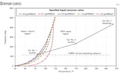
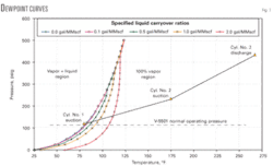
As Fig. 1 shows, the gas entering the low-pressure No. 1 cylinders exhibits large dewpoint shift with liquid entrainment, even at low to moderate scrubber liquid carryover. This readily explains why the liquid dropout in the No. 1 suction bottles is so much greater than in the No. 2 suction bottles, which operate at a higher pressure where the dewpoint shifts are not so pronounced.
The suction bottles on the Nos. 3 and 4 cylinders are immediately downstream of the discharge bottles from the Nos. 1 and 2 cylinders, respectively. The only possible source of liquids in these suction bottles is carryover of liquids with the gas discharging from the upstream cylinders. As described earlier, lab analysis shows these liquids to be lube oil diluted with condensate.
From the accumulated evidence, the deleterious effects of liquids ingestion on Big A/B can be reasonably inferred. For clarity, this discussion focuses only on the Nos. 1 and 3 cylinders.
Entrained NGL enters the No. 1 suction bottle, located on top of the No. 1 cylinder. From there, it enters the No. 1 cylinder and dilutes the cylinder lube oil. This causes a loss of cylinder lubrication, which imposes disproportionate forces on the bearings, resulting in excessive wear and premature bearing failures.
Diluted lube oil is then carried with the compressed gas into the No. 1 discharge bottle, located beneath the No. 1 cylinder. Fluids enter this bottle from the top and exit upward through a nozzle oriented about 45° from vertical. The No. 1 discharge bottle connects by a 6-in. diameter vertical pipe to the No. 3 suction bottle, located on top of the No. 3 cylinder.
Before installation of a drain line from the No. 1 discharge bottle, diluted lube oil would accumulate there because it had no way to escape. Once the level of oil in this 100-gal bottle increased sufficiently, liquid slugs would intermittently be forced out with the gas into the No. 3 suction bottle.
If and when a large enough slug was pushed out of the discharge bottle, it would enter the No. 3 cylinder, damaging the piston. Calculations indicate that a slug of only 4 gal would nearly double the pressure generated inside the No. 3 piston.
With respect to the two instances of cracked No. 3 pistons, the scenario just described cannot be absolutely proven, but it is consistent with the evidence. Both cracked pistons were on Big A. As the table in Part 1 shows, the volumes of liquids drained from the Nos. 1 and 3 suction bottles on Big A are more than seven times the volumes drained from the corresponding bottles on Big B. Also, no further piston damage has occurred since installation and daily operation of bottle drains.
Visual scrubber inspection
After discovery of liquids in the Big A compressor, fouled or damaged scrubber internals were initially suspected of causing excessive liquid carryover. Suction scrubbers V-5501 and V-5511 had not been opened in 10 years and were due for inspection, which occurred in August 2007.
Both scrubbers were clean, with all internals in very good condition. New mesh pads and vane packs were on site if needed. The existing vane packs were in nearly perfect condition and were not replaced. The existing mesh pads were only slightly worn, with no fouling or other damage. Because the mesh pads had to be removed to inspect the vane packs, new mesh pads were installed before the vessels were closed.
Scrubber inspections were performed by a Peerless Mfg. Co. representative. After no internal damage was found, Peerless recommended on line liquid carryover testing with a laser isokinetic probe. Specifications were provided for installation of 3-in. branch connections on the scrubber’s vapor lines to allow for probe insertion. WorleyParsons designed a mechanical piping package to install the required branch connections.
CFD modeling
On line carryover testing could not be performed until the required connections were installed on the scrubber’s vapor overhead lines during the next scheduled plant shutdown. In the interim, CDS Separation Technology, a subsidiary of FMC Technologies, was engaged to prepare CFD models to provide a better understanding of scrubber performance.
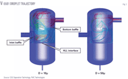
CFD model results indicate performance problems with both scrubbers. Scrubber V-5501 experiences significant recirculation and maldistribution of flow upstream of the mesh pad. This reduces volume utilization of the vessel, causing carryover of liquid droplets into the gas outlet.
Also, the inlet baffle plate diverts the feed stream downward onto the gas-liquid interface, which causes reentrainment of liquid particles and interferes with liquid level detection and control. Fig. 2, a snapshot from the V-5501 CFD model run, shows this inlet feed diversion and corresponding flow maldistribution. The model predicted that volume utilization for this vessel was 63.5% and that most liquid droplets smaller than 50μ were carried into the gas outlet nozzle.
Similar results were reported for V-5511. Volume utilization was 81%, higher than for V-5501 due to a lower mean vapor velocity that results in less internal turbulence. The overall liquid carryover rate, however, was predicted to be higher than for V-5501 due to a lower density difference between the liquid and gas phases.
The CFD models did not provide precise predictions of liquid carryover leaving the scrubbers. This would have required accurate modeling of the vane pack assemblies, which would have significantly increased both the complexity of the models and the time and computing resources required to run them.
Laser sampling
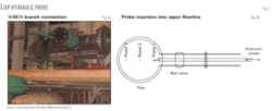
Branch connections for on line laser isokinetic sampling probe (LISP) carryover testing were installed during the summer 2008 plant shutdown. The test apparatus consists of a hydraulic sampling probe inserted through a 3-in. branch connection into the flowing vapor stream. Fig. 3 shows the actual branch connection for V-5511, alongside a Peerless sketch that illustrates insertion of the hydraulic sample probe into the vapor line.
A fluid sample flows through the hydraulic probe into an external LISP module, where two separate tests are performed. First, a laser-based particle counter yields particle size distribution and total liquid entrainment values. Second, the extracted sample flows through a coalescing filter that captures all entrained liquids and solids. Total entrainment is determined by weight difference of the filter elements.
Peerless Mfg. provided equipment and personnel to perform this testing in August 2008. Tests were conducted on each suction scrubber under two conditions, with only Big B running (half rate) and with both Big A and Big B running (full rate). Peerless issued final test reports in October 2008.
With only Big B running, liquid carryover was 1.37 gal/MMscf for V-5501 and 4.32 gal/MMscf for V-5511. For comparison, the performance guarantee for these two vessels is 0.1 gal/MMscf, which is a typical industry guarantee. With both Big A and Big B running, liquid carryover was 0.11 gal/MMscf for V-5501 and 4.56 gal/MMscf for V-5511.
Each of the four test results reported a substantial volume of “solids” carryover. These are not necessarily solids but represent the total mass of entrained fluids that do not vaporize after the samples are cooked for 8 hr at 190° F. No analysis was done, but brown staining of the filters indicates these solids are most likely entrained lube oil, which does not vaporize at 190° F. Compressor lube oil gets into V-5501 with the Big A/B recycle stream and into V-5511 with the discharge stream from the No. 3 cylinders.
Results for V-5501 show substantially more liquid and solids carryover with Big B running alone than with both Big A/B on line. This most likely indicates the poor turndown performance typical of vane packs, which depend on the difference in momentum between gas and liquids for effective separation. At lower flow rates, the liquid particles have less momentum and tend to stay with the gas rather than be captured on the vane surfaces.
During the 1995 plant expansion, the original vane packs were replaced with new vane packs designed to handle 48 MMscfd. A rate of 19 MMscfd with only Big B running corresponds to a turndown ratio of 40%.
Results for V-5511 show slightly higher liquid carryover and considerably higher solids rate with only Big B running than with both compressors on line. This again is consistent with reduced separation efficiency for vane packs at lower flow rates, but the difference is substantially less than for V-5501. Also, the much higher carry- over rates for V-5511, compared with V-5501, confirm the earlier CFD model prediction.
The V-5501 test with both compressors on line is the only one that even comes close to the vessel performance guarantee of 0.1 gal/MMscf. This result does seem strange, considering that substantially higher volumes of liquids are routinely drained from the suction bottles downstream of V-5501 than from the bottles downstream of V-5511.
On the other hand, the gas leaving V-5501 is richer than the gas leaving V-5511 and is more prone to condensation in the suction bottles and piping downstream of the suction scrubber. Regardless of this anomaly, this series of tests confirms that current scrubber performance is inadequate to provide clean, dry gas to the Big A/B compressors.
Lube oil replacement
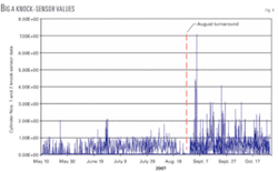
Plugging of small-diameter lubricator lines led to replacement of the synthetic lube oil used for Big A/B cylinder lubrication with mineral oil during the August 2007 plant turnaround. This change stopped the line plugging but had an unintended consequence. Fig. 4 plots Big A knock-sensor values for several months before and after the turnaround. Because no other changes were made during the shutdown that could account for the step change in knock-sensor output, the lube oil change out was the prime suspect.
Samples of mineral oil and synthetic lube oil were sent to a local lab for solubility tests with n-pentane. At room temperature, both lube oil samples were found to be completely soluble in pentane over a wide range of pentane concentrations. Mixtures of 75% lube oil and 25% pentane were then placed in a ventilated oven for 1 hr at 113° F., which is 16° F. above the boiling point of pentane.
As expected, this caused evaporation of pentane from the mixtures, but the total volume of pentane that evaporated was vastly different for each of the two lube oil samples. After heating, the synthetic oil mixture contained 4.96 wt % pentane, compared with 12.13 wt % pentane in the mineral oil mixture. This equates to a retention of 22% of the original pentane in the synthetic oil, compared with 59% retention of original pentane in the mineral oil.
In other words, at the lab test condition of 113° F., the mineral oil retained more than 2.5 times as much pentane as did the synthetic oil. At higher temperatures, this disparity in solubility between the two oils would be even greater. As a point of reference, the temperature inside the Nos. 1 and 2 cylinders on Big A/B ranges between 80-175° F.
The increased solubility of NGL in mineral oil compared with synthetic oil can be explained in terms of both chemical and thermodynamic properties. The relatively low solubility of pentane in the synthetic oil sample is largely due to its chemical formulation, which is proprietary. The particular oil formerly used at Milne Point, however, is primarily a mixture of poly-alpha-olefins and poly-isobutylene, the latter being responsible for the low NGL solubility.
From a thermodynamics standpoint, HYSYS process simulations confirm the lab test results. The existing Big A/B compressor suction scrubbers do not provide adequate vapor-liquid separation. This results in a mixed-phase compressor suction stream (gas plus entrained NGL). As shown previously in Fig. 1, this liquid entrainment shifts the dewpoint temperature of the gas-liquid mixture upward by an amount that depends entirely on the actual level of entrainment.
If there were no interaction between the entrained NGL and the cylinder lube oil, then these entrained liquids would vaporize early during each compression stroke as the cylinder temperature increased above the elevated gas dewpoint. In actuality, however, lube oil does interact with entrained NGL, as the lab tests showed that both synthetic and mineral oils dissolve and retain pentane.
Compared with the relatively minor dewpoint shift without NGL-lube oil interaction, whenever lube oil is dissolved in entrained NGL, even at low concentrations, the dewpoint temperature of the compressed gas shifts dramatically upward. This means that NGL components that would otherwise vaporize during the compression stroke will remain in the liquid state during the entire stroke.
The degree to which this phenomenon occurs largely depends on the type and concentration of dissolved lube oil. Because mineral oil has a much higher affinity for NGL than does synthetic oil, it can be expected to absorb and retain NGL to a much greater degree. This is consistent with the observed knock-sensor trends, which showed a step change increase after the August 2007 lube oil change.
In response to particularly high knock readings in November 2007, operators shut down Big A for inspection, which revealed a con rod bearing failure. This failure was almost certainly related to loss of cylinder lubrication caused by lube oil dilution with entrained NGL, exacerbated by the change from synthetic to mineral oil just 3 months earlier.
Research into the original plugging problem with synthetic oil indicates that a bad batch of oil from the manufacturer may have been responsible. Because in-line demisters will be installed to remove entrained liquids from the compressor suction streams, however, there are no immediate plans to switch back to synthetic oil for Big A/B cylinder lubrication.
Mineral oil is successfully used in reciprocating compressors all over the world and is expected to perform with no negative side effects at Milne Point once entrained liquids are no longer a problem.
