Accelerated amine-solvent change improves gas plant performance
Eric Teletzke
INEOS Americas LLC
Donald G. Norton
Coastal Chemical Co. LLC
Tyler Westerman
Jeff Fields
Kinder Morgan CO2 Co. LP
A natural gas liquid (NGL) treater using monoethanol amine (MEA) to remove carbon dioxide (CO2) and hydrogen sulfide (H2S) accumulated high levels of CO2 degradation products, reducing the capacity of the MEA solvent at Kinder Morgan Inc. subsidiary Kinder Morgan CO2 Co. LP’s gas plant near Snyder, Tex.
During operation with elevated levels of CO2 degradation products, the liquid treating system experienced corrosion failures on process equipment and operational upsets including amine-hydrocarbon emulsions.
A team of engineers from INEOS Americas LLC’s GAS/SPEC business unit evaluated the system and determined that a formulated solvent could meet the treated liquid specification and increase treating capacity with reduced circulation rate compared to MEA. The solvent also would not be susceptible to the CO2 degradation chemistry observed with MEA.
Economic justification for a solvent conversion limited the time the liquid treater could be taken offline to 5 hr. With on-site support from the amine supplier and the amine distributor, the team achieved a complete solvent changeout in 2.5 hr. Subsequent sampling of the new solvent revealed no residual MEA or CO2 degradation products in the system. Since converting to the new amine solvent, evidence of corrosion observed with MEA is no longer present, particulate filter replacements have been less frequent, and process upsets have subsided.
Background
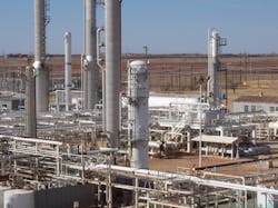
Snyder gas plant holds the original casinghead gas processing contract for what is known as the Scurry Area Canyon Reef Operators Committee (SACROC) unit, a field comprised of about 50,000 acres, of which Kinder Morgan owns a majority working interest.

Discovered in November 1948, SACROC is one of the largest and oldest oil fields in the US, using CO2 flooding technology since January 1972 to arrest oil production decline following waterflood recovery. About 1.5 bcfd of near-pure CO2 is produced from Bravo Dome, Doe Canyon, and McElmo Dome fields in Colorado-New Mexico, and pipelined to various Utah, New Mexico, and West Texas enhanced oil recovery (EOR) projects, including SACROC. In 2016, SACROC produced about 29,300 b/d and processed over 1 bcfd of gas, from which NGL production averaged about 20,900 b/d.1
More of a gas processing complex than a conventional gas plant, the Snyder plant includes:
- 64 feed gas and CO2-reinjection compressors.
- Solid-adsorption bulk dehydration for feed-gas dew point temperature control.
- The world’s first successful CO2 membrane plant for bulk CO2 removal.
- Amine systems for final acid-gas removal and recovery for field reinjection.
- Molecular sieve units for cryogenic-level dehydration.
- Cryogenic processing for NGL extraction to Y-grade pipeline sales.
- Drip and membrane condensate stabilization and amine treating for NGL pipeline sales.
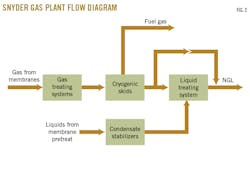
- A power cogeneration plant to consume the remaining residue natural gas (Fig. 1).
Since 1998, as EOR projects expanded, the Snyder gas plant was called upon to treat and process additional produced gas from the surrounding gathering systems. To accommodate process and operational upgrades on front-end and reinjection compression, low-level gas dehydration, and membrane unit expansions, gas plant adaptations included:
- An amine conversion of the original gas treating unit that ultimately added multiple formulated amine solvent treating systems for the complex.
- Additional sieve dehydration capability for incremental cryogenic processing.
- Cryogenic processing modifications and expansions.
- Supplemental drip and membrane condensate liquids stabilizer capacity.
- Expansion and modernization of control rooms and control systems.
The original NGL-MEA liquid treating system had redundant absorber and regeneration systems. During expansion, incremental stabilizer liquids were successfully treated without the need for capital projects. To maximize processing capacity and production, membrane operations were altered to shift the CO2 split between the permeate gas stream fed to the amine treaters and the hydrocarbon condensate stream ultimately fed to the stabilizer systems, adding incremental CO2 treating load to the MEA system. This system reached its maximum capacity in terms of production treating rates and equipment loads and sizing, amine chemistry and corrosion thresholds resulting in increased maintenance, equipment repair, and operating costs.
Fig. 2 shows a block diagram of the Snyder gas plant.
A decision needed to be made between a capital project to add more equipment or an upgrade to the amine chemistry of the existing unit to handle current and future expansion treating requirements. While installing a new, parallel treating train would have required minimal shutdown and tie-in time, it would entail substantial capital cost and equipment lead time. An amine solvent conversion from MEA to a formulated solvent offered an inexpensive option compared to new capital expenditures, but would require time to drain the system, clean and wash process equipment, and reload the system inventory with fresh amine.
An outage would be costly due to the high value of the revenue streams affected, but the current MEA system had reached its technical and operational limits. Incremental operational expenditure reductions for an amine system conversion would have to offset associated lost revenue from any outage as well as the conversion’s solvent and labor costs.
An operational window finally opened, allowing up to 5 hr of downtime on the liquid treater system to complete a solvent changeout from MEA to GAS/SPEC solvent. Plant personnel had to complete the conversion with minimal MEA and degradation cross contamination to the new system for maximum future-treating performance.
Solvent change evaluation
GAS/SPEC technical service engineers visited the Snyder plant to evaluate the liquid-sweetening system and determine if changes could be made to improve operations and protect the plant from further corrosion.
Ineos engineers noted that recent increases in the NGL rate and overall CO2 processed by the system had resulted in higher CO2-removal requirements. These increased requirements pushed the system to capacity in terms of amine-circulation rate and reboiler heat duty. The high volume of NGL and amine flow in the liquid treater was also exceeding the recommended 15 gpm/sq ft flux guideline for liquid-treating systems, indicating a potential for hydraulic issues resulting from the high combined-volumetric flow rate through the contactor.2
Without a thermal reclaimer present, degradation of the MEA solvent further reduced system loading capacity, increasing corrosion rates. Options for minimizing corrosion with the current MEA solution were limited to increasing MEA replacement rates or adding corrosion inhibitors to the system. The corrosion-inhibitor option was viewed as a last resort if process or operational changes couldn’t solve the corrosion issues present in the MEA liquid-treating system. Installing a thermal reclaimer was also an option, but the capital expense involved made that option undesirable.
INEOS liquid-treater modelling tools were used to compare performance of a fresh charge of MEA solvent with the same GAS/SPEC solvent that the Snyder gas plant uses in its gas-treating systems.
INEOS modelling indicated that GAS/SPEC solvent would provide increased capacity over MEA, while being able to treat the NGL liquids to Copper Strip 1 levels on a copper strip test under an ASTM testing procedure used to determine if sulfur compounds in a particular hydrocarbon product present a corrosion risk to copper fittings. The GAS/SPEC solvent is a formulated methyldiethanolamine (MDEA) solvent, which doesn’t form hydroxyethyl imidazolidone (HEI) or any other MDEA-CO2 degradation products. As a tertiary amine, MDEA cannot form the carbamate ion believed to be central to creating the new carbon-nitrogen bond present in amine-CO2 degradation products.3
MEA solvent concentrations are typically limited to a maximum of 20 wt % as increased corrosion rates have been observed with MEA concentrations above 20 wt % in service without corrosion inhibitors.3 GAS/SPEC solvents can operate at higher concentrations than MEA without an increase in general corrosion rates. Ineos recommends limiting the amine concentration for GAS/SPEC solvents in liquid treaters to 40 wt % to minimize amine solubility losses.
The ability to operate at a higher amine concentration with the formulated solvent provides the potential for increased capacity and-or reduced amine circulation. The ability to operate within loading guidelines at a lower circulation rate also provides a reduction in the liquid volume flux through the contactor, which could be contributing to hydraulic issues at rates > 15 gpm/sq ft. Using the GAS/SPEC solvent would allow for the same volume of NGL to be processed as MEA with only 50 gpm of amine-circulation rate. This would bring the tower within the < 15 gpm/sq ft volume flux recommendation and reduce the potential for upsets in the liquid contactor.
The formulated solvent provided an option that would improve system reliability and reduce operating costs in the long term, but a conversion would require upfront costs including the solvent, labor, solvent-disposal cost, and production down time.
To minimize the overall costs of the conversion, management determined a maximum window of 5 hr would be available in which the NGL treater could be taken offline. With that goal in mind, operations began working with Ineos and Coastal Chemical Co. LLC to outline a conversion procedure that would allow the changeout to take place within the allotted timeframe and ensure sufficient removal of the old MEA solvent and degradation products.
Planning, preparation
A Gannt chart with actions outlined down to the minute allowed accurate prediction of the time required for changeout. Kinder Morgan operations met with Ineos and Coastal Chemical the day before the changeout to review and finalize the procedures. Kinder Morgan indicated that the procedure would be considered a success if the changeout was completed in the 5-hr window, and if the residual MEA and degradation products were reduced to < 0.5 wt% of the total solution.
Three frac tanks were brought on site for the conversion: one tank for the reverse-osmosis (RO) rinse water, one to hold the amine solution blended to 40 wt %, and one to be used for the waste water-MEA solution drained from the system. The frac tanks were connected to the system via pneumatic pumps.
Fig. 3 shows the arrangement of the pneumatic pumps.
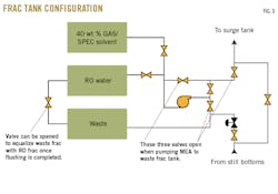
This arrangement allowed the same pneumatic pumps to be used to drain the spent MEA and to charge the system with flush water and fresh GAS/SPEC solvent blended to 40 wt %.
The Snyder plant has the advantage of two parallel regeneration systems (East and West), which helped minimize the treating downtime required for a solvent conversion. Before the conversion, the liquid treater was operating using only the West Regeneration system. To bring the new amine solvent online as quickly as possible, the East Regeneration system was charged with fresh solvent at 40 wt %. The East Regeneration system would then operate on hot standby until the MEA was drained from the liquid contactor and the formulated solvent could be brought online. This allowed the conversion to proceed without having to wait for the fresh solvent to be heated to the required operating temperature in the regenerator.
An important aspect of completing a solvent swap in an accelerated timeframe is making sure that as much of the contaminated amine solvent is removed from the system as possible. Operations walked down the piping and equipment to identify any low spots where MEA could become trapped. Procedures were developed for draining all the dead legs in the amine system during the swap to ensure MEA was cleared from these lines.
All of the carbon and particulate filters were shut in and drained, while all standby pumps—including charge and booster pumps—were drained and flushed to prepare them for online service. One particulate filter was drained, flushed, and left empty until the flush water had passed the filters. This fresh filter would be put in service after the system water flush, and the other filters would be taken out for replacement.
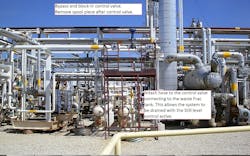
The morning of the changeout, the system operated using only the West Regenerator. Operations prepared the system to drain the MEA solvent (Fig. 4). The level control valve on the regenerator was blocked in and bypassed to install a connection to drain MEA to one of the on-site frac tanks. The level control leg was locked out and tagged out (LOTO) so that a spool could be pulled downstream of the level control valve and the connection to the frac tank could be installed. Once the connection to the frac tank was installed, the LOTO control leg was removed. With the LOTO component removed, the bypass leg was closed and the MEA solvent began to drain from the system with the regenerator level-control valve controlling flow to the frac tank.
The changeout
Starting the MEA bleed preceded setting the liquid-contactor level control to manual. Amine flow to the contactor was increased to drop the level in the surge tank and increase the level in the amine contactor. Amine flow to the contactor was increased slowly to prevent an emulsion from forming that could result in hydrocarbon-amine entrainment. As MEA was bled from the system, operations continued to treat NGL in the liquid contactor for 30 min as remaining MEA was flushed.
Fig. 5 shows data from the plant’s distributed control system screen as the conversion progressed.
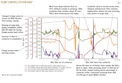
Once the surge tank reached a level at which the amine charge pumps were no longer able to pump, the surge tank and associated piping was drained using pneumatic pumps connected to the surge tank at designated connections (Fig. 6). Once the surge tank and associated piping were clear of residual MEA, operations began flushing the lines and surge tank with fresh RO water from the frac tank, with drains around the charge pumps remaining open through the RO water flush. After the surge tank and piping had been flushed and a new level was established in the surge tank, a charge pump was turned on maximum flow. Flush water was pumped through both charge pumps to ensure that bodies of the pumps were flushed.
About 15 min after the amine charge pumps lost MEA feed, NGL liquids were diverted from the liquid-treating contactor. The inlet block valve was shut in and NGL bypassed the liquid contactor. The NGL outlet of the liquid-treating contactor valve was left open to maintain pressure on the liquid contactor. This was important as the open valve allowed treated NGL to displace amine lost when draining the old MEA solution. Maintaining pressure on the NGL was essential to ensuring the NGL would not flash.
With the NGL liquids diverted from the contactor, amine flow out of the contactor was increased. Flush water then circulated through the system for 30 min at a rate of 150 gpm. A drain leg at the bottom of the liquid contactor was opened to monitor the liquids leaving the bottom of the contactor. The liquids initially were monitored based on color. The contaminated MEA solution had a purple tint as a result of the soluble chromium in solution. Once the color of the liquid drained from the contactor turned from purple to clear, a sample of the liquid was collected to test for amine concentration. Alkalinity concentration testing of the flush water drained from the contactor took place until amine was no longer detected in the flush water.

Amine flush water drained from the in-service filters was also tested until amine could no longer be detected. Once clear, those filters were blocked in and the standby filter was put into service. Flushing continued for 15 min after placing the new filters in service. Once the filters had been flushed with wash water, pumps were lined up to bring in the preblended 40 wt % GAS/SPEC solvent from the frac tank storage.
As fresh amine was fed into the system, flush water continued to drain from the bottom of the West Regenerator. This continued until an increase in concentration was observed in the flush water drained from the system. After the fresh amine had been flowing in to the NGL contactor for 15 min, NGL flow was reestablished into the contactor. The NGL liquid flow to the contactor had only been offline from 7:00-9:30 a.m., a total of 2.5 hr
Bringing the NGL flow online, allowed redirection of the rich amine flow to the East Regeneration system on hot standby. The West Regeneration system was blocked in and shut down. Fresh amine was added to the system via the frac tank connection until levels were reestablished in all process vessels.
Operations
After completing the solvent changeout, operations collected a sample of lean amine to verify that the residual MEA and MEA-degradation products had been removed from the system. Multiple samples collected after the conversion showed undetectable levels of MEA and HEI as measured by gas chromatography-mass spectrometry.
Fig. 7 shows amine analytical data from before and after the conversion.
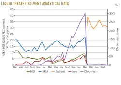
As anticipated, no HEI or CO2 degradation products have formed since converting to the formulated solvent.
The accelerated timeframe for the conversion allowed only a 30 min water wash and a 45 min dilute-amine rinse to clean the system before adding the fresh solvent. Operations set a goal of leaving less than 150 gal of the degraded MEA solution in the system during the changeout. Based on the system volume, a chromium reduction to < 10 ppmw in the analytical samples would indicate this had been achieved. The chromium level after the changeout was 6 ppmw.
In subsequent months of operation, the chromium remaining in solution trended downward, and iron was undetectable. Additionally, the purple coloration of the amine, characteristic of chromium, did not return following the conversion.
In addition to the reduction in soluble metals observed in analytical results, Kinder Morgan’s Snyder liquid-treating system has seen reduced filter changeouts and operational upsets in the months following the conversion.
Fig. 8 shows the decrease in filter-replacement frequency since conversion to GAS/SPEC solvent.
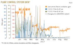
Because the conversion was completed on an accelerated schedule, there was an expectation that some residual solids would remain in the system following the conversion. These solids would gradually be filtered out during operation, a trend that can be observed as the filter replacements continue at a high rate initially following the conversion but one that decreases considerably as those residual solids are removed from the system (Fig. 8). The reduction in particulate-filter replacements in combination with the reduction in soluble iron and chromium in solution indicates that the corrosion observed with MEA has stopped following conversion to the new solvent.
NGLs produced at the Kinder Morgan Snyder gas plant must pass a Copper Strip 1 classification under ASTM’s testing procedure. Several sulfur compounds present in hydrocarbons will cause a positive result, including H2S, elemental sulfur, wet carbonyl sulfide, and organic polysulfides. It has been demonstrated that as little as 1 ppm of H2S can cause copper strip testing to fail Level 1 classification.4 Since the solvent conversion, treated liquids produced by the Snyder plant have consistently passed copper strip testing with a 1 Classification.
References
- https://www.kindermorgan.com/pages/business/co2/eor/sacroc.aspx.
- Sargent, A., and Seagraves, J., “LPG Contactor Design and Practical Troubleshooting Tips,” presented at the 53rd Laurance Reid Gas Conditioning Conference, Norman, Okla., Feb. 23-26, 2003.
- Kohl, A.L., and Nielsen, R.B., “Gas Purification,” Fifth Edition, Gulf Publishing Co., Houston, 1997.
- Clark, P. D., and Lesage, K. L., “The Copper Strip Corrosion Test—Understanding and Supplementing It,” presented at the 41st Laurance Reid Gas Conditioning Conference, Norman, Okla., Mar. 4-6, 1991.
The authors
Eric Teletzke ([email protected]) is a senior gas treating engineer and territory manager for INEOS GAS/SPEC Technology Group, where he specializes in the design, operation, and optimization of amine systems for applications including shale gas processing, LNG, refining, tail gas units, liquid treating, and carbon capture. Previously he worked as a process engineer at Honeywell International Inc. He holds a BS (2007) from the University of Texas at Austin.
Donald G. Norton ([email protected]) is a senior engineering consultant at Targa Resources Corp. With over 40 years’ experience in the oil and gas industry, he has held a variety of engineering positions with refining and natural gas processing companies. He played a key role in the Kinder Morgan Snyder liquid treater conversion as a senior technical service engineer with Coastal Chemical Co. LLC. He holds a BS (1975) from the Georgia Institute of Technology and is a registered professional engineer in Texas.
Tyler Westerman ([email protected]) is engineering manager for Kinder Morgan Inc.’s SACROC gas processing plants. His previous roles at Kinder Morgan have included 4 years as a process engineer and 4 years serving as plant manager of the Snyder gas plant. He holds a BS (2009) in chemical engineering from the University of Kansas.
Jeff Fields ([email protected]) is a maintenance supervisor for Kinder Morgan Inc., where he has served with the Snyder gas plant operations team for more than nine years. He has over 35 years’ experience in the midstream sector including, 17 years in operations, 12 years in maintenance, and 6 years in a supervisory-management role.