HPPT restoration, redesign enhance integrity, efficiency at Saudi complex

Amro K. Al-Abbasi
Sultan H. Al-Owaidhi
Ashiff Khan
Saudi Aramco
Dhahran
Following repairs to damaged oil train internals discovered during a 2016 turnaround and inspection (T&I) of its 1.2-million b/d Khurais Central Processing Facility (KhCPF) in Saudi Arabia, Saudi Aramco undertook a project to improve future mechanical integrity and separation efficiency at the complex via a redesign of the trains’ high-pressure production trap (HPPT) internals.
Along with reducing water carryover to downstream vessels at the site, restoration and upgrading of the internals’ design has enhanced separation efficiency in the HPPT by more than 60%, It has also resolved mechanical issues that previously damaged internal equipment.
Background
KhCPF consists of four identical oil trains designed to process wet crude oil and associated gas for separation into dry and stabilized crude oil, high-pressure gas, and disposal water. Each train consists of one HPPT, one low-pressure production trap (LPPT), a dehydrator, desalter vessels, and a crude stabilizer.
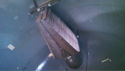
The inlet nozzle directs incoming crude entering the separator (Fig. 1).
As one of Aramco’s largest vessels (170 ft in length and 26 ft in diameter), the HPPT is a horizontal three-phase separator made of SA516 Gr.70, hydrogen induced cracking (HIC)-resistant carbon steel. With a nominal vessel thickness of 27 mm, the HPPT has a design pressure of 100 psig but operates at 50 psig. Wet crude coming from the inlet-production manifold enters the HPPT via a 48-in. inlet nozzle equipped with a vane-type inlet device (Fig. 1). The inlet device reduced momentum of the incoming fluid to achieve initial separation at the entry point of the vessel.
The HPPT is also fitted internally with two stainless-steel coalescing plate packs to enhance water separation by enabling water droplets to merge and coalesce to form droplets of larger diameter, increasing the settling velocity and enhancing separation (Fig. 2). The vessel includes 15 high-temperature zinc anodes for cathodic protection and corrosion-monitoring purposes.
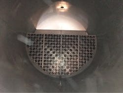
Vessel internals include two stainless-steel coalescing plate packs (Fig. 2).
Collapsed internals
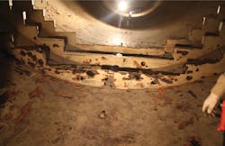
During the 2016 T&I of KhCPF’s oil trains, Aramco discovered an HPPT’s inlet device had collapsed, with the coalescing plate pack scattered around the vessel shell (Fig. 3). Contact between the carbon-steel vessel shell and the stainless-steel internals (inlet device and coalescing plate pack) had resulted in galvanic corrosion, which in turn reduced the vessel’s wall thickness at the worst corroded location to 6 mm from 27 mm. Aramco also observed many scattered corrosion points of varying thickness that rendered the vessel completely unfit for operation (Fig. 4). The damage required immediate extensive repair work to restore the vessel to operable condition.
Most of the affected areas were repaired by weld buildup techniques, and locations in shell courses with low thickness were replaced with a circular plate using an insert-plate technique of appropriate size, thickness, and material.
One mandatory phase of the repair procedure thoroughly reviewed was a post-weld heat treatment (PWHT), required per Aramco standards following major welding repairs. Because of the PWHT, Aramco expected to observe thermal expansion in the direction of the vessel inlet and fixed saddle, as well as vessel expansion of 100-150 mm due to thermal effect.
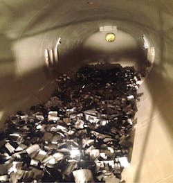
During 2016 T&I activities, the team discovered damaged vessel internals (Fig. 3).
Aramco observed more than 900 corrosion pits and leaks across the vessel shell (Fig. 4).
Executing the PWHT required lifting the vessel above the saddles using temporary supports to allow free expansion. To calculate impacts during the PWHT, Aramco observed vessel contraction during the cooling process and carried out finite element analyses (FEA).
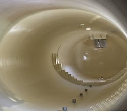
After completing nondestructive testing, coating application of the vessel, and the hydrotest, Aramco installed sacrificial anodes and conducted an electrical continuity test between the anodes and the vessel structure. Both filling and draining operations during the hydrotest also were thoroughly monitored to ensure water quality and temperature were maintained and the water used for filling and draining were handled properly. Following hydrotesting, an American Society of Mechanical Engineers (ASME)-authorized inspector accepted the vessel’s repair work, and the vessel received an ASME “R” stamp and certificate of authorization (Fig. 5).
Aramco restored the vessel to working order before completing studies for redesign of its internals (Fig. 5).
After the vessel’s safe and successful repair, Aramco’s team investigated root causes of the problem via performance analysis that relied on detailed Lean Six Sigma tools (OGJ, Dec. 5, 2011, p. 102). Focusing on all potential causes, the team identified several possible factors related to process, inspection, and vessel design. The evaluation concluded the one likely root cause of the HPPT’s failure, as well as subsequent corrosion and metal loss, was a collapse of the inlet device, resulting in damage to the coalescer packing. Specifically, the study concluded the inlet device was not properly designed and installed to handle extreme process conditions of slugs and surges from long trunklines.
The study prompted Aramco to recommend operating the HPPT without the coalescing plate pack to assure vessel integrity while it revisited the internals’ design.
Design studies
The team started engineering activities and design of new HPPT internals by studying the inlet-production header flow profile to the vessel inlet. It next performed an actual slug-flow study using a densitometer to explore behavior of flow towards each HPPT and determine the presence and magnitude of slug forces that may reach the inlet devices. The slug-flow study was followed by a computational fluid dynamics (CFD) study to analyze fluid flow in a geometry and an FEA study to quantify the impact of forces on a geometry.
• Inlet-production header flow profile assessment. This study evaluated possible flow conditions in the wet-crude inlet network that could damage HPPT inlet devices. The motivation for this study was inlet devices falling from their supports inside KhCPF’s multiple HPPTs and subsequent damage to the internal coalescer plate pack.
The inlet configuration at KhCPF includes 14 trunklines, which transfer multiphase wet crude from remote manifolds to KhCPF. Each trunkline feeds into the four production trains’ headers and to a line toward the depressurizing vessel. The four production headers transfer the crude to HPPTs for initial separation.
Aramco considered several operational scenarios and modes during the study to accurately quantify the maximum slug forces in the inlet line, such as facility shutdown and startup, slugging from the trunklines into the headers, slugging during normal operation, and surge during pipeline scraping. Several other operating conditions also were measured during the test. Hydraulic simulations were carried out using Olga software to model flow behavior inside the headers and estimate possible slug forces that would occur at the separator inlets.
Analysis of a large data set spanning 2.5 years allowed determination of events that could have propagated large slugs within the inlet equipment, damaging inlet separator vessels. Hydraulic simulations modelled flow behavior inside the headers to determine maximum slug forces. The main forces at KhCPF’s inlet were of two types: the continuous repetitive force caused by hydrodynamic slugging generated within the headers and the surge force caused by sudden opening of the inlet valve near the oil train inlet when a large pressure differential was present. The forces caused by slugging during normal operation were estimated at 80-140 kN at normal-flow rates and as high as 130-230 kN at high-flow rates, depending on GORs. In the case of surges caused by the inlet valve opening at a large pressure differential, the force could reach around 330 kN, as observed in an actual case during a previous unplanned shutdown at the complex.
• Densitometer slug measurement. Slugs in the piping were measured using two nucleonic densitometers at a known distance from each other. Clamp-on densitometers were used to avoid interfering with the process. Density as a function over time was measured at both locations, with density peaks (slugs) determined in each measurement and coupled. (Fig. 6). The time delay combined with the known distance yielded the slug velocity. The measurements confirmed the magnitude of the slugging occurring in the headers. Slugs were observed every 2 min with peak slugging every 15-20 min.
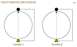
After on-site measurement results verified Olga software data on dynamic slugs, Aramco determined the Olga simulation for the inlet-valve opening case was reliable for subsequent detailed assessments.
• CFD analysis. Compared with traditional methods like field measurements, CFD is a powerful tool for analyzing fluid flow in a geometry using simulation to calculate and visualize flow. The vessel manufacturer used Olga software results on slug velocity as input for CFD modelling. The CFD results (maximum pressure as function of location) served as input for FEA, the results of which were later used as a design basis for new HPPT internals and supports. The study also considered isometrics of inlet piping and its affect on the inlet device.
The CFD study sought to replicate maximum pressure and forces on the internals occurring during a worst-case slug. Since the HPPT internals (inlet device and coalescing plate pack) had their own specifications, HPPT geometry was split into two separate CFD models.
The extreme, worst-case input used for CFD modelling was a velocity of 19.5 m/sec at 100% water density. CFD analysis showed a resulting total force in longitudinal direction of 463.7 kN. Due to asymmetric inlet piping in the vessel, the force in transverse direction was not zero, but -34.6 kN.
• FEA. FEA is useful in studying the impact of forces on a geometry by calculating internal forces and stresses. In combination with CFD results, FEA can calculate stresses placed on a solid material by a flow (e.g., slug flow on the inlet device).
The FEA study sought to study stresses in the internals and supports under load conditions as determined by the CFD study during a worst-case slug.
FEA simulations showed that the inlet device and its support structure had sufficient strength to resist the extreme load condition based on CFD pressures, assuming an inlet velocity of 19.5 m/sec at full-water density.
Old vs. new design
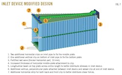
The old inlet devices were not designed for extreme slugging conditions. The new design, however, can handle slugs consisting of 100% water at an extreme velocity of 19.5 m/sec with additional safety margins. This case is caused by the upstream inlet-valve opening without pressure balancing, as the high differential pressure across the valve with a sudden opening will result in the maximum amount of slug force.
Fig. 7 shows major design enhancements to the old inlet device following the CFD and FEA assessments.
Restoration and redesign of KhCPF HPPTs’ internals improved separation efficiency by more than 60% and reduced water carryover to downstream vessels.
Internal visual inspection of the vessels 1 year after upgrading and redesigning their internals showed the inlet device and coalescing plate pack in secure, working order, with no signs of movement.
Recommendations
Based on its experience at KhCPF, Aramco now recommends performance of both CFD and FEA in designing internals for vessels at processing sites receiving crude oil from a production field. In the case of brown field projects, an actual slug measurement is necessary to identify the maximum forces affecting the vessel and appropriately design vessel internals. For design of vessel internals for greenfield projects, the slugging effect should be estimated using appropriate modelling and simulation techniques to prevent equipment damage.
Misalignment and dimension differences between a vessel’s as-built drawings and actual site measurements always should be avoided and be confirmed during site installations.
Additional materials and a contingency plan also should be made available to on-site personnel to eliminate prolonged downtime in the event of an upset. Manufacturer supervision also must occur during installation to assure no problems arise.
Acknowledgment
The authors would like to extend their appreciation to Saudi Aramco for providing its cooperation as well as the resources required to complete and publish this study.
The authors

Amro K. Al-Abbasi ([email protected]) is plant engineering supervisor in Saudi Aramco’s Khurais producing department. During his more than 8 years at Aramco, he has held various leadership positions, including compliance group leader, operations and maintenance foreman, and group leader for oil, gas, and utilities plant engineering teams. He was also a member of Saudi Aramco Young Leader Advisory Board (YLAB). Al-Abbasi holds a BS (2008) in electrical engineering and an MBA (2010) in engineering business management, both from University of Warwick, UK. A Lean Six Sigma Green Belt, he is a member of several international societies and has published at several international conferences.

Sultan H. Al-Owaidhi ([email protected]) is lead plant engineer for crude oil trains in Saudi Aramco’s Khurais producing department. His responsibilities include providing technical support to operation and maintenance personnel and executing process enhancement assessment. He holds a BS (2015) in chemical engineering from King Fahd University of Petroleum and Minerals, Dhahran.

Ashiff Khan ([email protected]) is a senior process engineer in Saudi Aramco’s Khurais Central Processing Facility and was the lead engineer for oil trains during this major repair and redesign of HPPT and its internals. He holds a BS (2002) in chemical engineering from University of Calicut, Kerala, India, as well as a post-graduate degree (2011) in management and and Masters in Law (IP) (2013), both from Indira Gandhi National Open University, New Delhi, India. An American Society of Safety Engineers certified HAZOP chairman, Lean Six Sigma Green Belt, environmental management system professional, and safety auditor, Khan is also a chartered engineer and registered member of the Institution of Engineers, India.