Amine-unit startup illustrates commissioning considerations
Thomas Wieslaw
Consultant
Lake Charles, La.
Norman P. Lieberman
Process Improvement Engineering
Metairie, La.
Effective startups usually stem from efficient scheduling and attention to detail during project design and commissioning. While commissioning of typical amine units can be straightforward, a disconnect often may exist between design and real-world operating conditions. The earlier this disconnect is discovered, the easier startup becomes.
In 2015 an Indian refiner commissioned an amine methyldiethanolamine (MDEA) unit to remove acid gas (carbon dioxide, CO2) from low-pressure gas feedstock as part of a broader refinery expansion project.
During and following initial startup, the unit experienced a series of operational issues. While the MDEA unit has since achieved optimal and consistent operations, the troubleshooting process highlighted important considerations applicable to design and startup-commissioning of acid-gas removal systems.
This article uses the authors' amine-treating experience at the Indian refinery and from previous assignments to outline a detailed approach to identifying and troubleshooting sources of common operational issues with monoethanolamine (MEA) and MDEA-based amine units. It also presents relevant unit design and precommissioning techniques that can be employed to streamline startup.
Technology selection
CO2 absorption by amine solutions is a reversible process, the equilibrium of which depends on factors such as the temperature, concentration, and circulation rate of the amine solution, as well as the partial pressure of CO2 in feed gas.
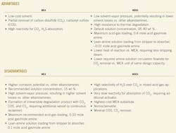
The gas treatment industry uses, among others, the alkanolamine solutions MEA and MDEA to absorb CO2 and hydrogen sulfide (H2S) from acid gas. MEA is a primary amine because only a single carbon atom bonds to the nitrogen atom (i.e., only one hydrogen atom in the ammonia molecule is replaced). Because they have a higher heat of reaction and are more alkaline, MEA solutions tend to be more reactive and require more stripping steam than MDEA solutions.
With MDEA, a tertiary amine, all hydrogen atoms in the ammonia molecule are replaced by carbon. These tertiary solutions are more sterically hindered, resulting in lower reactivity, lower alkalinity, and slower reactions. MDEA solutions also are virtually noncorrosive. MDEA, however, must be combined with a special vendor-provided activator to enhance its reaction kinetics with the acid gas targeted for removal.
The accompanying table compares advantages and disadvantages of using MEA and MDEA in gas treatment applications.
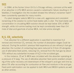
The reaction of CO2 with primary MEA doesn't stop with formation of one stable product in the rich amine. Acid-loaded MEA solutions react further to form diamines and other byproducts such as carboxylic acids. Over time, these byproducts make amine solutions even more corrosive and result in hydrogen-assisted stress corrosion cracking (SCC) on vessels and piping at welds, requiring the MEA unit to operate at limited amine concentrations as a form of mitigation (Box 1).
The Indian refiner selected MDEA to remove CO2 from its low-pressure gas feedstock for the following reasons:
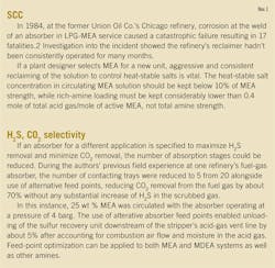
• MDEA's ability to operate at a higher concentration and higher values of acid gas (CO2) mole/mole of amine loadings-i.e., pure amine, not the solution-enabled a 39% lower flowrate of MDEA solution vs. MEA solution based on the amine unit's design.
• Due to its tertiary nature, MDEA's heat of solution with CO2 in the absorber tower was lower (575 btu/lb) than MEA's (825 btu/lb), allowing for lower steam requirements in the stripping section.1
• MDEA's slow reactivity could be addressed by adding piperazine, an activator, to enhance MDEA-CO2 reaction kinetics.
• Feed-gas pressure to the absorber was designed to 2 barg, whereas MEA solutions tend to have high vapor pressures that can lead to major vaporization losses, especially in low-pressure operations.
• MDEA is relatively noncorrosive.
Unit overview
The refinery's amine plant design centered around performance of the absorber tower, which like most in the industry, has a bottom and top section. In the bottom section, feed gas to the unit is counter scrubbed with lean-amine solution before moving to the top section where, past the chimney tray, the gas is washed with demineralized water to remove any entrained amine solution and, if necessary, reduce its temperature. To ensure the unit could meet its design capacity for acid gas removal, packing was used throughout the absorber based on its superior turndown capability vs. trays, as well as its tendency for more flow capacity and lower pressure drops than trays in towers with a similar diameter and similar CO2-scrubbing efficiency.
From a design perspective, proper vapor-liquid distribution is critical if packing is used throughout an absorber. Unlike trays, packing does not redistribute either vapor or liquid, which can lead to channeling and poor contacting efficiency between the two phases. To avoid these problems, a channel-type gravity lean-amine solution distributor (e.g., a multi-through distributor with slotted tubes) is preferable to spray nozzles, which often require a pressure drop across the distributor. On the gas side, a chimney-tray distributor with adequate pressure drop (e.g., a minimum of several mm mercury) creates good gas distribution, especially when using a half-open feed pipe for gas entry into the column. Packing-bed depth should not exceed 15-20 ft.
The Indian refinery's unit required more packing area in the low-pressure absorber. The packing bed was divided into two bed areas, with a vapor-liquid redistributor installed between them.
When operating below designed feed-gas rates, a typical MDEA unit's amine-solution circulation rate (both lean and rich) can be slightly lowered to achieve designed acid gas (CO2) mole/mole of amine circulation and save on steam requirements during solution regeneration in the stripper. It's important, however, to never reduce reboiler duty to the point where vapor traffic cools off. Such cooling could leave the operator unable to maintain requisite amine levels in the reflux drum. A unit's amine-flow turndown also could be limited by mechanical requirements such as pump turndowns or flow requirements for packing spray coverage in the absorber.
Fig. 1 shows a diagram of the Indian refinery's MDEA unit.
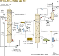
Process flow
Rich charged MDEA collects in the bottom of the absorber column and is pumped to a CO2 stripper by the rich-amine solution pump, while a level control maintains the column level. The unit's rich-amine solution pumps, both running and spare, are equipped with minimum-flow protection to prevent spillback to the absorber. Before reaching the stripper, rich-amine solution is preheated by lean-amine solution in the crossflow plate-and-frame heat exchanger. Amine solution flashes into the stripper column across the absorber's level control valve, with valve placement downstream of the exchanger helping minimize vaporization of gases in the plate-and-frame exchanger.2 The stripper operates at a pressure of about 0.7 barg, with the kettle-type reboiler supplying the heat required for stripping.
To adjust duty, a temperature controller partially floods the reboiler tubes with condensate, while a temperature indicator located at the top of the column (above the reflux-return line) provides feedback to the temperature controller. To prevent steam breakthrough, a low-level steam condensate pot will override the temperature controller. On the overhead vapor line, an exchanger condenses vapor to liquid.
Gas-liquid separation occurs in the reflux drum, liquid from which flows to the stripper via a level control. The pressure control valve at the reflux drum's vent line controls tower backpressure, while offgas vents to an atmospheric incinerator.
The heat energy required for amine regeneration in the stripper raises the temperature of feed solution to the temperature of lean solution leaving the reboiler, reverses the amine-CO2 gas reaction and dissociates the amine-CO2 compounds, and vaporizes reflux water into steam to serve as stripper vapor.3
Heat exchanged with rich-amine solution in the crossflow plate-and-frame exchanger cools lean-amine solution from the stripper before it is sent for further cooling by temperature-controlled exchangers. A cool lean-amine slipstream is routed for mechanical and carbon filtering by packed absorbers to scrub particulates entrained in feed gas that, if not properly removed, can cause fouling and foaming in the unit.
Since water balance always affects MDEA concentration circulating through a unit by saturating treated gas from the absorber and CO2 offgas from the stripper-which, over time, leads to system water loss-makeup water added to the absorber's washing section can be increased to attain the required MDEA strength.
If, however, a unit experiences amine loss caused by high vapor saturation at the vapor outlet of the stripper's reflux drum, less makeup water may need to be added.
While treated gas can remove water from a unit by increasing the temperature of lean-amine solution fed to the absorber, it is important to limit the temperature difference between feed gas to the absorber and treated gas. Temperatures of feed gas and lean-amine solution fed to the absorber should closely match to prevent high losses or oversaturation of solution. Saturation levels of treated gas exiting the unit can be adjusted by changing the temperature of cooling wash water in the absorber tower's wash section.
The temperature of lean-MDEA solution entering the absorber should be 50-60° C., as a temperature below 50° C. may slow the rate of CO2 absorption due to decreased reaction speed. At lower temperatures, however, even with a higher potential for absorption, a short residence in the packed absorber will not be enough to reach required CO2-removal targets.
Precommissioning
Parallel commissioning of the MDEA unit and gas refining project enabled the refinery to increase efficiency of precommissioning works, which included testing of electrical, mechanical, and partial operational systems by methods such as valve and leak checks, pressurization, and lean and rich-amine pump runs.
Because corrosion and foaming are common and serious problems for even the most well-designed amine units, prestartup activities at the new MDEA plant focused on treating its stainless-steel vessels and equipment to mitigate against corrosion and fouling mechanisms.
• Step 1. The absorber was degreased using a hydroflush of low-chloride water. Before flushing, vortex breakers, bottom degassing packing, and orifice plates in liquid lines were removed, and manholes in the tower column and tanks were opened.
• Step 2. After the operations team ensured that amine-solution pumps to the absorber were not blocked by grease and grime, strainers were installed on the pumps' suction-sides to prepare the absorber for a potassium carbonate wash (about 3 wt %) treatment. This also provided a good opportunity both to test control valves and safety interlocks and to test the unit for leaks by pressurizing the system with nitrogen to 80 kPag.
• Step 3. For the potassium carbonate wash, a low-chloride solution of potassium carbonate was introduced at the stripper's bottom and the stripper was pressurized with nitrogen. The solution was circulated in the system using a 10-hr rotation between both primary and spare rich and lean-amine solution pumps (extra time should be taken, if available) at 50-60° C. Before emptying the system, a few samples of potassium carbonate solution were taken from different locations within the unit for visual inspection. The samples showed a relatively clear solution, so no additional washing was required. The solution was neutralized for disposal and drained from the unit.
• Step 4. After reinstalling bottom degassing packing and orifice plates removed ahead of the Step 1 degreasing, the system was filled with clean, treated water circulated at 60° C. under the unit's designed flow conditions using primary and spare rich and lean-amine solution pumps. Because this clean-water circulation wash previews how water from the unit would react with fresh MDEA solution, a sample of water was taken from the unit and mixed with a sample of MDEA matching the unit's designed amine-solution concentration. Results of a foam test (described below) showed no indication of foaming. If the clean water-MDEA solution mix had shown signs of foaming, a second clean-water wash would have been required.
• Step 5. The system next was purged with N2 to bring the oxygen concentration below 0.4 vol %.
Using an activated carbon bed that processes an amine side slipstream (10-20% of main lean-amine flow) is a good way to ensure an oil and particulate-free solution throughout the entire unit. An improperly commissioned carbon bed, however, can lead to increased foaming.
Because of its highly porous nature, the activated carbon bed was filled in batches. The vessel was filled first with 30% treated water and next with 30% of required activate carbon by volume. After the activated carbon became saturated, additional batches of water and carbon were added. During the saturation period, the vessel was vented. Supply water temperature was increased to help expedite filling of carbon internal pores.
To eliminate any particles in the bed that could be carried out with solution and cause foaming, a temporary 1-in. purge-water stream was added to the bed's bottom to act as a temporary backwash. The water overfilled the tank and carried out small, unsaturated particles. The water flow rate was set low enough (at 0.15 cu m/sq m) to prevent lifting of the particles
Unit operation
After pressurizing the absorber and stripper tower, MDEA-solution circulation was established. During this startup phase, feed-gas flow initially bypassed the absorber by setting the bypass valve at 100% open. The absorber's motorized inlet and outlet isolation valves then were slowly opened, which was followed by a slow closing of the bypass around the absorber.
If feed gas had been introduced to the column all at once, CO2 absorption would have been almost instantaneous. Such an initially high-removal rate of CO2 (constituting about 15-30% concentration in feed gas) would have caused a decrease in forward flow of treated gas from the absorber as well as a sudden loss of pressure to downstream units.
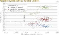
Absorber temperature profile
As CO2 absorbs into and reacts with the MDEA solution in the absorber, the heat of reaction increases the solution's temperature as it descends the column. While the amine solution transfers some heat to the feed gas at the absorber's bottom, feed gas ascending to the top of the absorber is cooled to a temperature within a few degrees of the lean-amine solution entering the absorber. A majority of the heat of reaction, then, is removed by the rich-amine solution pump at the absorber's bottom. The temperature of rich-amine solution increases as acid gas (CO2) mole/mole of amine loading increases.
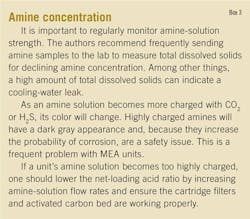
During the MDEA unit's startup, up to 0.23 moles of acid gas (CO2) were removed per mole of lean-amine solution entering the absorber (Fig. 2). The temperature of rich-amine solution exiting the absorber was about 7° C. higher than the inlet lean-amine solution and about 12° C. higher than the entering feed gas at 0.2 CO2 mole/mole of amine, suggesting an uneven temperature profile, or bulge, inside the absorber (Box 2).
Process control issues
The MDEA unit entered operation well below design conditions because of limited feed-gas availability, which caused the reboiler temperature to oscillate and become unstable at various stripper loads.
Located at the top of the tower near the return-reflux tray, the column's temperature controller required different tuning parameters at different loads. The different parameters avoided swinging the reboiler duty and column pressure and leaving the pressure controller to try and catch up.
Erratic changes in tower pressure can cause liquid reflux to boil and create a surge of vapor at different sections in the packing when vapor is at dew point. To remove the need for various sets of tuning parameters, a cascading feed-forward control was temporarily added to set steam flow to the reboiler based on the rich-amine solution flow rate and unit-tested ratio of kg of steam/cu m of rich amine solution, ensuring sufficient stripping of CO2 in the previous test runs.
Investigation showed that placement of the temperature controller too close to the reflux inlet-line nozzle caused the erratic temperature swings. The tower-top temperature controller subsequently was relocated to the stripper column's overhead line during the unit's shutdown for routine maintenance.
Units where the stripper's pressure is floating on the inlet pressure of a downstream unit (e.g., a sulfur recovery unit) should use an alternative reboiler steam-control mechanism. Given otherwise stable conditions, a tower with floating or oscillating pressure also will have an inherent change in the tower-top temperature. Instead of using temperature to control reboiler duty, reboiler steam flow should be adjusted to achieve a reflux ratio setpoint of 12 g of water/l. of lean amine (0.10 lb/gal) exiting the stripper. Maintaining a good top-reflux rate also reduces reboiler-tube corrosion rates caused by occasional rich amine entering the reboiler.
The MDEA unit eventually achieved acid gas (CO2)-loading mole/amine circulation at 0.33 mole CO2/mole amine with an average stripping ratio of 60 kg of steam/cu m of amine solution (0.5 lb of steam/gal of amine solution), a medium-pressure steam, and an MDEA-solution concentration of about 32 wt % (Box 3).
Fouling, foaming
The MDEA unit includes two plate-and-frame exchangers working in parallel to cool and heat the lean and rich-amine solutions, respectively. Over time, the exchangers showed signs of fouling as the pressure drop and temperature approach began to increase. A sample of the fouling residue revealed evidence of iron sulfide and iron carbonate. These compounds result from reactions of saturated feed gas with high amounts of CO2 and carbon-steel piping feeding the unit.
Because of their tight spacing, plate-and-frame exchangers often serve as very effective filters. As differential pressure eventually increases, however, they require cleaning to remove accumulation of sticky, black dust. Each plate must be cleaned individually, as any material left or missed during cleaning could cause the plate gasket enabling separation of hot and cold fluids to leak upon resealing the exchanger.
During the unit's routine maintenance, the gaskets were removed and each groove cleaned before reattachment to prevent leaks.
MDEA-unit design did not include upstream filtration on rich-amine solution exiting the absorber. This filtration typically is left out to avoid handling acid-gas charged amine when opening the filters for maintenance. Excessive particulates from iron sulfide and iron carbonate, however, can stabilize and cause foaming in the amine solution (Box 4). Feed gas to the unit contained <10 ppm H2S. But any amount of the accumulated black dust is pyrophoric and requires special safety precautions.Particle-size analysis established the need to install, upstream of the cross exchanger, a mechanical mesh filter able to drain, purge to the flare, and withstand high-pressure cleaning to remove wet scale-sludge.
Amine losses
Amine loses can occur in both the absorber and stripper column. In the absorber, frequent causes of such losses include accumulation of particulates because of poor filtration, undersized downcomers in tray towers, high amine strength, and excessive acid-gas loading.
In the stripper, fitting a reflux drum that runs on total reflux with a reflux purge can draw off excess water from steam leaks in the reboiler or cooling water in the condenser. This reflux purge will contain a small percent of amines that will be lost when the water is drawn off.
The absorber's feed-gas inlet pipe and lean-gas outlet from the waterwash contained isolation valves. In between the isolation valves, there was a small column bypass that adjusted CO2 levels to maintain the absorber's outlet-CO2 specification for the gas plant. To avoid amine solution flowback into the feed-gas line during periods of high amine levels in the absorber, typical units contain an elevated, goosenecked feed-gas pipe above the feed-gas distributor (Fig. 4).
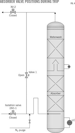
During initial operation of the MDEA unit, the absorber experienced amine-solution carryover into the inlet line through the gooseneck pipe whenever the gas plant tripped or forward gas flow was interrupted.
A shutdown of the upstream gas plant prompted checking the absorber's initial amine-solution level to ensure it wasn't too high. Excess solution can spill into the distributor. A second investigation involved verifying there was no foam inside the absorber, preventing potential buildup above the distributor.
Eliminating both a high amine level and foaming as cause of the carryover prompted investigation of a new theory based on observations made during initial commissioning, this one involving unit design.
While the absorber's inlet and outlet isolation valves were designed to close in the event of a plant upset, the absorber bypass line downstream of the feed isolation valve remained open. Amine-solution circulation through the absorber also continued as it would during normal operations.
During a plant trip, the isolated absorber would slowly lose gas pressure as amine entrained some gas and carried it to the stripper. Allowing the absorber's internal bypass to remain semiopen during the plant upset enabled pressurized gas inside the column to establish a natural vapor flow from the absorber's bottom up through the column bypass, entraining some liquid-amine solution still flowing down the packing.
A nitrogen purge installed downstream of the absorber bypass, modified to now close in the event of an interruption at the upstream gas plant, tested the design-based issue as a possible cause of the carryover problem. The newly added nitrogen valve was configured to open if the absorber's inlet and outlet isolation valves closed to give the distributor a small forward purge.
During the next trip of the upstream gas plant after the modifications, the unit no longer experienced amine-solution carryover, allowing the refiner to maintain amine-solution circulation without issue as it waited for the upstream plant to resume operations.
References
1. Jonassen, O., Kim, I., and Svendsen, H., "Heat of Absorption of Carbon Dioxide (CO2) into Aqueous N-Methyldiethanolamine (MDEA) and N,N-Dimethylmonoethanolamine (DMMEA)," Energy Procedia , Vol. 63, 2014, pp. 1890-1902.
2. Lieberman, N.P., Troubleshooting Process Operations, 4th Edition, PennWell Corp, Tulsa, 2009.
3. Kohl, A. and Nielsen, R., Gas Purification, Gulf Publishing, Houston, 1997.
The authors
Thomas Wieslaw ([email protected]) is a principal engineer for ethylene technology at Sasol Ltd. in Lake Charles, La. Specializing in olefins, gas-liquids processing, and reforming units, his 10 years' experience includes roles in daily operations, troubleshooting, commissioning, and plant process design. Wieslaw was acting as a consultant when he did the work described in this article. He holds a BS (2007) in chemical engineering from the University of Illinois at Urbana-Champaign.
Norm Lieberman ([email protected]) is a chemical engineer with 53-years' experience in plant operation, design, and field troubleshooting. He served as operations supervisor, technical service manager, and plant manager at US refineries until 1985. An independent consultant, he has taught 800 seminars on troubleshooting refinery process problems to 19,000 engineers and operators. Author of nine textbooks on plant process problems and operations, he holds a BS (1964) from Cooper Union, New York, NY, and an MS (1965) from Purdue University, West Lafayette, Ind., both in chemical engineering.
Foaming
Whether primary or tertiary, amines are prone to foaming. Caused by particulate matter in the amine solution, foaming reduces mass-transfer efficiency of the packing or trays and can result in the carryover of solution with the treated, or sweetened, gas.
Evidence of foaming includes:
• Increased pressure drop across the packing or trays.
• Unsteady flow on a continuous rich-amine spillback.
• Liquid-level control difficulties.
• Increased CO2 in treated gas (given all other normal conditions).
• Insufficient residence time in downcomers for vapor disengagement (i.e., flooding).
• Discrepancy between amine-solution levels in the vessel and gauge glass.
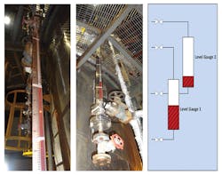
Evidence of discrepant amine-solution levels was found during commissioning of the Indian refinery's MDEA unit (Fig. 3). A single-level gauge in the absorber will not detect foaming.
The following steps can be used to test for foaming in a unit:
• Pour a 200-ml sample of lean-amine solution into a 600-ml cylinder and add a diffusor stone, which can be obtained from the amine supplier.
• Bubble a constant nitrogen flow through the diffusor stone in the solution for about 6 min.
• After determining the final foam level in ml, remove the stone from the cylinder.
• Determine the time required for the foam to break down. A foam level of about 400 ml with a breakdown time < 35 sec is considered normal.
• Use the same procedure to compare initial foaming results on a fresh solution sample with results of tests run on samples of solution that have experienced runtime in the unit.
To reduce the occurrence of foaming, dose the unit with an antifoam agent and clean unit filters. Silicone-based antifoam is very effective in suppressing foaming and flooding in any type of amine absorber or stripper, but do not overdose the unit. Antifoam is a surfactant, and adding too much can exacerbate the foaming.
While troubleshooting the Indian refinery's MDEA unit, high dosing with antifoam also once resulted in choking of side-stream filters with organic compounds. Antifoam was adsorbed by the carbon bed, reducing the bed's capacity to adsorb both organic compounds and other degraded chemicals from the circulating amine solution.