Beyond back-to-basics: Process principles and concepts—11 | Averting dangers of automated controls

General Introduction
Geared to young and seasoned professionals alike, “Beyond back-to-basics: Process principles and concepts” is a series of articles designed to present a straightforward approach to mastering the principles and concepts all process engineers should be able to apply without the need of a computer.
While simulations and models are useful for examining long-term operational issues, they cannot replace the dimension of human logic and reason required when tackling the array of complex—and sometimes life-threatening—situations that occur in process plants.
Using experiences from the author’s more than 50-year career in the process industry, articles in the series provide approaches to understanding core process concepts in ways that will equip the engineer to walk out of an office, into a plant, and directly resolve process deficiencies via small operational changes or simple retrofits.
This is the eleventh article in the series.
Norman P. Lieberman
Process Improvement Engineering
Metairie, La.
The day before the Boeing 737 Max 8 flight crashed in Indonesia and killed 170 people in July 2018, I was on a Lion Air flight from Jakarta to Borneo, on a project for Indonesian refiner PT Pertamina. Based on reports of the incident, a flawed sensor in the aircraft was at fault.
The erroneous sensor was measuring the angle of attack which, if excessive, will result in aerodynamic stall. This flawed sensor, combined with the pilot’s understanding of how to disable the relevant computer control loop, resulted in the catastrophic crash.
The same scenario happened 8 months later in March 2019 in Ethiopia, where more than 300 airplane passengers were killed.
This article discusses the basic critical knowledge every unit operator should have about automated control systems to prevent similar catastrophic events in the refinery and processing plant setting.
Refinery process controls
As a former refinery operating supervisor and current refinery process troubleshooter, this sad story is unfolding in a familiar pattern. As I explained to my older sister, Arline, “It’s just the usual.”
“Norman, are you now claiming to be an expert in aeronautical engineering in addition to chemical engineering?”
“Well, dear sister, let me give you a few examples. I worked for American Oil for many years in operations, design, and technical management. Perhaps the most common similar incident in the refining industry is the raffinate splitter explosion at the former BP PLC refinery in Texas City, Tex., in March 2005 (OGJ Online, Mar. 20, 2007; Mar. 23, 2005). This tower was designed in the early 1970s, long before BP acquired the refinery.
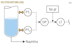
“The operators were tracking the splitter bottoms level, measured by differential pressure, (Fig. 1). This is the modern method of level measurement, as compared to the ancient, archaic, and obsolete method of the internal float arm.”
“How does that work, Norman? I mean, the differential modern method?” Arline asked.
“The two pressure transmitters (PT) generate a milliampere electrical output. The difference between the dual readings (DP) is then converted to a level based on a density (sp gr) assumed by the instrument technician at the same point in time for the naphtha.
“If the sp gr drops by 10%, however—perhaps because the naphtha is hotter or lighter than normal—the indicated level transmitted to the control center will not be the actual 80% but 72% (80% x 90%),” I explained.
“But, Norm, that’s not a very large error, is it?”
“Arline! Suppose the level rises above the top tap (PT1). While the pressure at the lower tap (PT2) increases, the pressure at the tap (PT1) will increase at the same rate (Fig. 1). When the real level in the vessel reaches the top tap (PT1), the level in the control center will read 90%. As the actual liquid level rises 1 ft, or 10 ft, or 100 ft above PT1 (the top tap), the indicated level in the control room will be stuck at 90%, and then…”
“Their cup runneth over!” Arline said.
“Yes, but the indicated level then draws a straight line at 90%.”
Manual intervention
“That absolutely straight line is the indicator to the trained operator that he or she is tapped out,” I explain to my sister.
“Can’t these guys and gals see the liquid level in their gauge glass, Norm?”
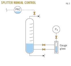
“No, Arline. Naphtha is water-white in color, and gauge glasses often are scratched. Finding the meniscus is very difficult, unless you can see movement in the gauge glass. My method is to switch level control to manual (Fig. 2). I then take the pressure difference between the tower-top pressure control transmitter (PRC) point and P3, and convert the differential pressure to feet above the elevation of P3: (PRC - P3) x (2.31) ÷ (sp gr) = height (in ft) above P3 elevation, where PRC = top pressure, psig; and P3 = pressure at top of upper gauge glass, psig.
“The challenge is to have the operators trained to execute these steps, especially to start running their raffinate splitter on manual until they can get their level transmitter recalibrated.”
Tower pressure control
“In April 1975, I was working in the former Amoco Oil Co. refinery in Texas City, where I oversaw the No. 2 alkylation unit, which produced 26,000-b/sd of high-octane gasoline. I had 40 people working for me, but one day as I was making my daily round on the unit, I noticed that a local pressure gauge was reading 450 psig (Fig. 3).
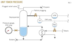
“Good God, I thought! The tower’s relief valve is set at 320 psig, its mechanical design pressure is 360 psig, and its normal operating pressure is 290 psig.
“I quickly checked the local gauge. It was correct. What had happened?
“After investigating, I determined that a corrosion-inhibitor chemical we’d been using had plugged both the depropanizer relief valve and the pressure sensing tap.
“Tower pressure was controlled by adding steam to the reboiler based on the concept that heat makes pressure. But the pressure-control signal to the steam supply of the reboiler and the high-pressure alarm (HPA) were both connected to the same pressure point of the tower, which was a recipe for disaster.
“I immediately switched the steam flow to the reboiler to manual, using the local pressure gauge as a temporary guide. I then connected the HPA to a different point on the tower than the PRC.”
Temperature control
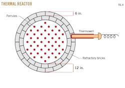
“During the 1980 strike in Texas City, I was working as the chief operator on the refinery’s sulfur recovery unit. I was starting up the unit myself after a very long shutdown. The unit’s thermal reactor had been retubed, and zirconium-silicate refractory inserts had been installed to protect the tube inlets from excessive temperature. These inserts, called ferrules, had a temperature rating of 3000° F. Normal thermal reactor temperatures were 2100-2300° F. This temperature was monitored by a thermowell inserted through the 12-in. alumina refractory bricks.
“During the start-up, a young female engineer on loan from the company’s research and development department in Chicago was assisting me.”
“‘Mr. Lieberman,’ she said, ‘those ferrules are glowing a yellow color. According to the color chart that we used in my combustion engineering class at Louisiana State University, those tube inlets are approaching 3000° F.!’
“‘Look here,’ I said. ‘I don’t need you to instruct me! I designed this sulfur plant myself. The local tube inlet is still quite cool at 1800° F. Turn up the gas. I know what I’m doing.’”
“But the thermowell housing for the local tube inlet had only been inserted halfway (6 in.) into the 12-in. refractory during the unit turnaround (Fig. 4). Hence, it was reacting to a temperature halfway between ambient and the actual thermowell reactor temperature of 3000° F. As the heat-up progressed, I couldn’t help but notice the ferrules inserted at the tube inlets seemed to be melting and restricting the small 1-1/2 in. tube inlets.
“And then, to confirm my worst fears, Arline, I noticed that the thermal-reactor inlet pressure was creeping up. Apparently, the overheated thermal-reactor inlet tube sheet was restricting the flow of the flue gas.”
“The refinery’s plant manager held me personally responsible for the sulfur recovery plant being offline for the next 2 weeks. But I’m much smarter now. Whenever an instrument or a control loop contradicts observed plant data, I now immediately switch from automatic to the manual mode of control.”1
References
- Lieberman, N.P., Troubleshooting Process Plant Control, 2nd Edition, John Wiley & Sons Inc., Hoboken, NJ, 2017.
The author
Norman P. Lieberman ([email protected]) is a chemical engineer with more than 50-years’ experience in process plant operation, design, and field troubleshooting. He previously served as operations supervisor, technical service manager, and plant manager at US refineries until 1985. An independent consultant, he also has taught 800 seminars on troubleshooting refinery process problems to 19,000 engineers and operators. He was awarded the Lifetime Achievement Award in 2018 by Hydrocarbon Processing. An author of nine textbooks on plant process problems and operations, he holds a BS (1964) from Cooper Union for the Advancement of Science and Art and an MS (1965) from Purdue University, both in chemical engineering.