Two-phase expanders manage feed-gas changes
Katarzyna Chołast
PGNiG SA
Odolanow, Poland
John C. Heath
Ebara International Corp.
Sparks, Nev.
| Based on a presentation to GPA Europe 30th Annual Conference, Sept. 18-20, 2013, Edinburgh |
Modification in 2003-04 of Polish Oil & Gas Co.'s (PGNiG) nitrogen rejection unit (NRU) at its natural gas and helium plant in Odolanow addressed a feed-gas composition that differed from the one for which the plant was originally designed in the 1970s.
The modification consisted of adding two-phase turboexpanders parallel with Joule-Thomson (J-T) valves, which then became standby for expanders being used during start-ups or shutdowns.
After nearly 10 years of service, this new process has proven easy to operate and controllable with no danger of shutdown even with considerable changes of feed-gas parameters. Operators can precisely adjust process parameters to maximize sales-gas output and helium recovery, minimize methane content in the waste gas, and withdraw up to 30 tonnes/day/train of LNG.
Poland NRU
A typical NRU consists of compact heat exchangers, pumps, cryogenic distillation columns, and J-T valves integrated to carry out efficient separation into the required products. J-T valves reduce the pressure of streams entering distillation columns in order to decrease the stream temperature and assist in providing refrigeration to the process.
PGNiG's Odolanow plant in southwestern Poland consists of two trains, each processing up to 136,000 normal cu m/hr of raw feed gas. Fig. 1 shows how one of the processing trains is linked to gas supply and sales-gas compression.
Raw gas flows from the plant supply header into each train. The first processing element is an amine unit that removes CO2 from the gas down to about 5 ppm (vol). The next process block is a thermally regenerated two-stage adsorption system with molecular sieves that remove water as the first stage, while the second stage, based on activated carbon, removes heavy hydrocarbons.
The dry gas then flows to the cryogenic unit, which separates nitrogen from the methane, producing high-btu sales gas that requires compression before being piped into the grid. In addition to nitrogen-methane separation, a stream of crude helium is produced that subsequently enters a helium purification and liquefaction process.
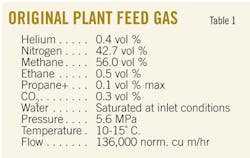
Table 1 shows the original incoming gas composition.
Sales gas from the plant had to contain less than 4% nitrogen, while the waste nitrogen, which was vented to the atmosphere, was to have less that 1% methane. In addition, helium recovery was required to be more than 85% with a final purity of 99.999% as liquid at –269° C. The original design required that the sales gas leave the cryogenic unit at about 1.8 MPa.
Over years of operation, the raw feed gas has gradually changed as old gas wells were depleted and new ones brought online to supply the Odolanow plant. The composition today has changed markedly with 32–34% nitrogen in the feed. In addition, the helium content has decreased to a little more than 0.2%.
Therefore, the refrigeration potential of the feed gas has been reduced because there is now proportionally less nitrogen to expand to near atmospheric and, by difference, more methane produced at 1.8 MPa. This has gradually caused more severe operational problems for the two plants.
In order to make up the "cold deficit," operators maintained plant stability by allowing a larger amount of methane to slip with the waste gas. This was clearly a temporary solution to maintain sales-gas output but resulted in damage to the environment and loss of revenue from the methane emissions. The plant was originally capable of producing small amounts of liquid methane or nitrogen for sale to third parties. All of this was severely impaired by the lower nitrogen content in the feed gas.
Furthermore, as the gas source depletes, the feed-gas pressure may require costly investment in precompression. It would also be desirable to improve the efficiency of the NRU operation so that even with the drop in the feed-gas pressure, there would still be enough cold produced to permit stable operation. The current feed-gas pressure—about 5.3 MPa—is being maintained by adding new gas sources.
As a result, various studies carried out in the late 1990s and 2000 addressed the problem and identified solutions. In addition, helium, the high-value product, has decreased in concentration in the feed gas. This made it imperative that any changes to the process not reduce helium recovery.
Cryogenic process
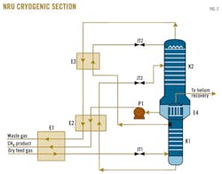
In the original process, all energy needed for natural gas separation in low-temperature units was provided by pressure reduction of the natural gas across J-T valves (Fig. 2).
The dry feed gas flows into the first exchanger (E1) of the cryogenic unit, which cools it at 5.3 MPa, condenses and subcools it before it passes through the first J-T valve (JT1) for expansion to the lower column (K1).
The pressure in the lower column is about 2.1 MPa, and thus there is some flash into the lower column. The rich liquid from the base of K1 is then subcooled in E2 against returning colder methane liquid and gaseous nitrogen streams to about -150° C. Then it passes through JT3 where the subcooled rich liquid expands to 0.12 MPa, thereby creating some flash before entering the upper column.
The upper column operates at about 0.1 MPa and carries out the main distillation between nitrogen and methane. Reboil to this column is provided by condensing nitrogen at 2.2 MPa in the top part of the upper column. This condensed nitrogen (high purity: <10 ppm methane) is drawn from a downcomer seal as a side stream from the upper column, subcooled in exchanger E3 before it is expanded across JT2, and admitted to the top of the upper column (K2).
This nitrogen stream provides the necessary reflux to purify the nitrogen waste gas, which returns through E3, E2, and E1, before being vented to atmosphere. Therefore, the expansion valves JT1, JT2, and JT3 provide all of the refrigeration to the process.
The methane product pump (P1) raises the pressure of the methane product to 2.08 MPa from 0.17 MPA before the methane evaporates and is reheated in E2 and E1. The methane product is then compressed to about 5.0 MPa to enter the grid.
Over the years, the Odolanow NRU plant has seen the nitrogen reduced to 33% now from 42%. Operators anticipated further reductions in nitrogen content. As nitrogen in the feed decreases, the amount of nitrogen reflux also decreases in proportion to the methane that enters the upper column. Consequently, the distillation process does not perform as well as before and methane content in the waste gas increases.
Concept development
The study led to selection of the most effective way of providing refrigeration to the upper column. Among other options, the analysis included the following:
• Separate cycle to produce cold to provide to the upper column.
• Gas expander after partially condensing the feed.
• Preseparation column or separator upstream of the double column.
• Extra trays in upper column.
• Import of liquid nitrogen to assist in cold production.
• Replacing JT1, JT2, or JT3 with expanders.
After study, adding an expander in parallel with JT3 appeared to be the most promising approach. JT3 then becomes a standby for the expander.
Expansion turbines are always more efficient because they carry out isentropic depressurization, which generates work instead of isenthalpic depressurization across a J-T valve, which generates no work. Turbines take energy out of the process, bringing about greater cooling of the streams passing through them, and thus increase overall process efficiency.
The choice of this location for an expander meant that the liquid entering the expander was well subcooled, ensuring a good quality single phase at the inlet. The outlet would produce 10–30 mole % flash, which was an unusual service. This translates to 80–95 vol % of liquid.
This issue presented two problems.
The first was the two-phase flow stability for a fluid rising to the upper column entry point for all the cases. The second, and by far the more difficult, was design of an efficient turbine that converted not only the hydraulic energy into useful work, but also the gas expansion energy.
The first issue was successfully addressed by correct selection of the fluid regime for all the likely scenarios, using specially designed piping and entry systems to prevent surges and vortices causing problems with pressure stability at the turbine outlet and flow stability at the upper column inlet.
The second issue was to obtain turbines able to expand into two phases. Test programs dating from the 1980s had confirmed this prospect, but no commercial application of the technology was found. Confidence that two-phase expanders would be feasible was established after an engineering study that was further supported by knowledge that:
• A similar duty was tested that used a Pelton wheel open expander in air separation.
• A "gas" type expansion turbine was tested with flashing liquid nitrogen.
• There was evidence that one of the Ebara International Corp. liquid expanders was producing flashing flow at its outlet because there was helium in the gas.
• There would be no cavitation in this situation because the conditions were expanding and not collapsing gas bubbles.
• There was evidence in the field that gas-oil separation at the wellhead had liquid expanders that were seeing two phases at the outlet.
The concept that was designed for the plant had a greater amount of flash than any of the above examples that represented the greatest challenge.
The expander was located to take feed upstream of JT3 and route it to the upper column to near the same entry point as before, except with a special arrangement for the piping. The liquid is well subcooled at that point because it leaves E2 at cooler than -150° C. and at a pressure of 2.1–2.4 MPa. The rich liquid contains about one-third nitrogen, the rest methane. Hence, when expanded to 0.24 MPa, it produces some vapor through the turbine.
It was decided that the Ebara turbine lent itself to exporting power because the generator is located inside the vessel that houses the turbine. Control of the unit was facilitated by variable speed, constant frequency (VSCF) turbine speed control that uses the level signal from the lower column (K1), making the expander act as a control valve.
In practice, this control method works well, and variable-frequency drives (VFDs), of which the VSCF is a derivative, have been used in many areas, including pump control at the Odolanow NRU. This site confidence helped in selection of this control route.
With the rich liquid cooled further than from the control valve (JT3), more cold is routed to the upper column, and the separation of methane from the nitrogen waste-gas stream is considerably more effective compared with the previous J-T arrangement.
Two-phase expansion
Two-phase expander design concepts fundamentally follow existing single-phase turbine and expander technology. The hydraulic energy of the pressurized fluid is converted by first being transformed into kinetic energy, then into mechanical shaft power, and finally to electrical energy through use of an electrical power generator.
The generator is submerged in the cryogenic liquid and mounted with the expander on a common shaft. The cryogenic induction generator uses insulation systems specifically developed for cryogenic service, giving superior dielectric and life properties to submerged windings. Lubrication for the bearings is by an internally designed system that takes a small portion of the liquid passing into the turbine and routing it to the bearings.
This produces some inefficiency, but the design of this system is far simpler than the typical external oil lubrication system. This was another feature of the "canned" turbine design because the revamp required a smaller plot area and fewer connections to the main process with no need for seal gas.
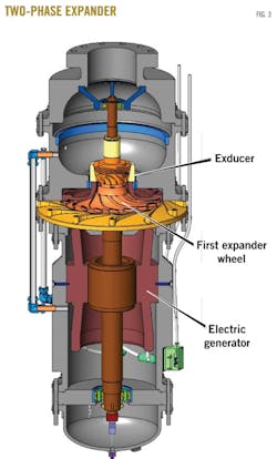
Fig. 4 shows the cross-section of a typical Ebara cryogenic two-phase submerged expander. The expander consists of a nozzle ring generating the rotational fluid flow, a radial inflow reaction turbine runner, and a two-phase jet exducer.
Symmetrical flow is achieved in the two-phase expander by use of a vertical rotational axis to stabilize the flow and to minimize flow-induced vibrations, with the direction of flow being upward to take advantage of the buoyant forces of the vapor bubbles. (Expanders with horizontal rotational axes generate asymmetric flow conditions that can result in higher vibration levels.) The hydraulic assembly is designed for continuously decreasing pressure to avoid any cavitation along the two-phase flow passage.
Field experience
To upgrade low-methane natural gas by extracting undesired nitrogen, the operator installed two Ebara two-phase expanders (one on each train, located in parallel to JT3; Fig. 2) at the Odolanow NRU (Fig. 3). During optimization, modifications were made to the turbine runner and exducer in order to enhance power output and hence cold production.
From October 2004 to third-quarter 2013, the expanders have been running with unchanged arrangement and configuration.
Table 2 presents the operational statistics for the two expanders M110/1 and M110/2 (one on each train). Operational experience of the two-phase expander technology suggests the following:
• The expanders required limited modification of the existing equipment, and consequently their installation is normally easy and retrofitting can be done quickly. They operate without being heard while working with neighboring equipment of average noise level below 80 db.
• The employed expanders have made the process flexible in terms of its adjustment to changing mass flows, varying 60-100% of nominal duty. Even with such considerable changes, they ensure precise regulation of level in the lower columns of both trains, which is valuable for stable running of the process. The two-phase expanders operate at variable speeds in order to adjust to the changing mass flows and pressure conditions of the plant.
Use of the presented method allows nitrogen and methane separation even with short-term CO2 increases without additional CO2-removal steps. The employed liquid two-phase expansion turbine can accept short-term higher CO2 concentration with no danger of plugging or consequent shutdown of the NRU.
This added tolerance is only temporary because the plant would have to be thawed out later in any case. While one would not design a new plant in this way, it gives operations staff more flexibility and a greater on stream time.
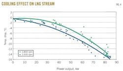
• Cooling the methane-rich liquid feed to the upper column is more efficient with two-phase expanders than with single-phase expanders or other devices. Fig. 4 presents the LNG temperature drop vs. the power output for the previously described two-phase expander, and the cooling effect on the LNG stream is seen to be directly related to the power output.
Due to the greater temperature difference achieved by the expander, the heat exchangers (particularly E3) operate more efficiently and flexibly, thus minimizing the danger of heat sinks.
• Use of this two-phase expander in place of JT3 allows the sales-gas product from the NRU to be at considerably higher outlet pressure, increasing by about 0.2 MPa.
The benefits of this have appeared as lower compression requirements downstream of the NRU, thus with lower fuel-gas consumption per compressed unit. It means that the methane pumps can operate at a higher discharge pressure than before.
In addition, the efficiency of the described process allows for running it at a lower feed-gas pressure. In case of reduced pressure of the feed gas from depleting sources, one could postpone the decision to install an expensive precompression step.
• The NRU can produce either liquid nitrogen or LNG for sale to third parties. With the expanders operating, there is a large increase in LNG output from the NRU of up to 250% compared with when J-T valves, JT3 in Train 1 and Train 2, were operating. Alternatively, the plant was able to produce similar quantities of liquid nitrogen for export.
Both LNG and liquid nitrogen can be withdrawn from the double-column arrangement into vacuum-insulated storage tanks for loading into road tankers and export.
In addition, while the original design was for 42% nitrogen in the feed, with the 33% now, the waste-gas methane content rose to more than 3% with poor plant stability and frequent operator intervention.
Because of the higher efficiency of the described process employing Ebara liquid two-phase expansion turbines, the upper column feed is colder, which helps to cool the upper column's top section further, leading to a lower methane content in the waste gas (even down to 0.3%).
Also, employing liquid two-phase expansion turbines in the separation of nitrogen and methane will allow generation of energy that can be used for export or as a drive power for another duty.
And, finally, the high efficiency of the process allows the possibility of removing from it large amounts of low-pressure LNG or a liquid nitrogen stream, running the nitrogen methane separation in a stable manner at the same time. The possibility of producing LNG may be useful for the plants at which peak shaving is going to be applied.
Bibliography
Bond, Ted, "Replacement of Joule-Thomson Valves by Two-Phase Flow Turbines in Industrial Refrigeration Application", 2000, www.mpptech.com/techpp/tech_home.htm.
Boom, R.W. et al., "Experimental Investigation of the Helium Two Phase Flow Pressure Drop Characteristics in Vertical Tubes," Proceedings of ICEC 7, London, July 4-7, 1978, pp. 468-473.
Elliott, D.G., and Weinberg, E, "Acceleration of Liquids in Two-Phase Nozzles," Technical Report No. 32-987, Jet Propulsion Laboratory, California Institute of Technology, Pasadena, Calif., 1968.
Filina, N.N., and Weisend II, J.G., "Cryogenic Two-Phase Flow: Applications to large-scale systems," Cambridge University Press, 1996.
Gebhart, Benjamin et al., "Buoyancy-Induced Flows and Transport," New York: Hemisphere Publishing Corp. 1988.
Hays, Lance, "History and Overview of Two-Phase Turbines," International Conference on Compressors and Their Systems, London, Sept. 13-15, 1999.
Isalski, W.H., Separation of Gases, Monographs on Cryogenics 5, Oxford Science Publications, 1989.
Jones, J.K., "Upgrade Low BTU Gas," Hydrocarbon Processing, September 1973.
Ross, Greg, Davies, Simon, Vislie, Geirmund, and Hays, Lance, "Reductions of Greenhouse Gas Emissions in Oil and Gas Production and Processing by Application of Biphase Turbines," 1996, www.mpptech.com/techpp/tech_home.htm.
Shively, R.A., and Miller, H., "Development of a Submerged Winding Induction Generator for Cryogenic Applications," Proceedings of the IEEE Electrical Insulation Conference, Anaheim, Calif., Apr. 2-5, 2000.
Vislie, Geirmund, Davies, Simon, and Hays, Lance, "Further Developments of Biphase Rotary Separator Turbine," IBC Separation Systems Conference, May29-30, 1997, Oslo.
The authors
Katarzyna Cholast ([email protected]) is technical deputy director for the Polish Oil & Gas Co. in Odolanow in process development at the natural gas and helium plants. Since first being employed by the company in 1986, she has worked with at various positions, starting from an engineer in the technical office and including the sales and supply manager. She holds a masters of science from Wroclaw Technical University and an MBA from Wroclaw Univeristy of Economics. Cholast is also a member of the European Chapter of the Gas Processors Association.
John Heath ([email protected]) has worked for EIC Cryodynamics for more than 20 years and spent 34 years in the pump and expander industry. Now semi-retired, he provides market consultancy for research and development projects. He holds a degree from Loughborough University, UK.


