Tunneled pipelines in seismic zones need determined limit length
Liqiong Chen Yan Xia
Southwest Petroleum University
Chengdu, China
Xiaoyu Han
Beijing Institute of Technology
Beijing
Safely operating natural gas pipelines through inclined tunnels in seismic regions requires stress analysis research. Incline angle, inclined pipe length, cover depth, pressure, and temperature are among the factors affecting pipe stress. Proper consideration of these factors can determine limit length at varying incline angles.
The continuous expansion of long distance natural gas pipelines in China often encounters complex mountain landscapes requiring tunnel crossings. Some tunnels may cross seismic areas. Gas pipelines in tunnels that are damaged by an earthquake are harder to repair than general underground pipelines. Damage to them could also endanger people's lives and the environment.
This article analyzes the influence of various factors on pipeline stress in seismic zones and actions that can be taken to reduce this stress.
Stress-checking criterion
The main reference for stress checking a long-distance natural gas pipeline is ASME B31.8-2014.1 This standard divides the pipe into two types, embedded and non-embedded. The gas pipeline in the studied tunnel has both embedded and non-embedded characteristics. Under ASME B31, in continuous working conditions longitudinal stress is the primary stress, expansion stress is secondary, and accidental load stress is the combination of the accidental load and the sustained load.2
• Embedded pipeline. For the embedded pipeline, which includes the straight section of the buried pipe and the elbow and branch pipe in rigid soil or compacted soil, the checking criterion of primary stress and comprehensive stress is SL ≤ 0.9ST, where S is the minimum yield strength of the pipeline material and T is the temperature coefficient, the value of which is 1 when the temperature is less than 121° C.
• Non-embedded pipeline. For the non-embedded pipeline, which includes the embedded buried pipeline, the elbow and branch pipe in the compacted soil, and the overhead pipe fixed by rigid support, the checking criterion of the primary stress is SL ≤ 0.75ST.
Seismic loads are accidental loads (OCC) and regulation 833.4 in ASME B31.8 should be followed: the accidental-load stress produced in a short time should be less than or equal to the product of the minimum yield strength and temperature coefficient, SL ≤ ST.3
Boundary conditions
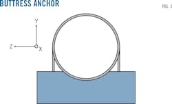
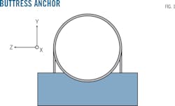
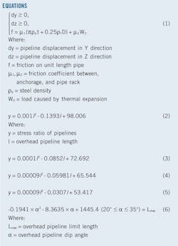
The buttress anchorage's main function is to support the weight of the pipe and limit its displacement in all directions except axial (Fig. 1). Equation 1 is the mathematical expression of the friction between the pipeline and the pipe rack and anchorage according to constraint conditions. The constraints in Y and Z direction are both unit constraints in the equation.
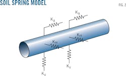
In covered pipeline sections the interaction between pipeline and soil is manifested in two main aspects: the axial friction between the soil and the pipe and the lateral thrust of the pipe. Stress analysis of buried pipelines simplifies the interaction between pipe and soil to axial soil spring and lateral soil spring (horizontal and vertical) connected to the node of the pipe element (Fig. 2), in which KA, KH, and KV express the spring coefficients in three directions.
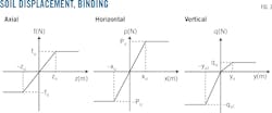
Fig. 3 shows the ideal relationship between soil deformation and binding, in which fu, pu, qu and zu, xu, yu present the yield force and displacement of a single spring element each. Soil deformation and pipeline binding is roughly linear. A Caesar II software simulation, the American Lifelines Alliance model,4 5 solved for soil stiffness and the maximum binding force.
The pipeline displacement on both sides of the fixed pier is independent and the stress change cannot be transmitted by the pier. Therefore, in the tunnel, the fixed pier on both sides of the pipeline is the boundary of the pipe model.
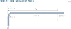
Interaction between the pipeline and soil divides the line into three regions (Fig. 4). Zone 1 is the area closest to the elbow, resulting in lateral displacement. Zone 2 is the transitional region and is less affected by the bending moment and only subjected to axial force. There is no relative displacement section in Zone 3, which will not produce axial displacement. Force analysis on any part of Zone 3 simplifies the boundary conditions on both sides as axial constraints at both ends.
Yan Yingshan tunnel
The Yan Yingshan tunnel near Baoshan, Yunnan province, China, is 1,840 m long with an initial downhill slope of 23.27° for 700 m. Overhead piers line this section of the tunnel with 10 m between each. An anchor pier was installed 5 m before the ramp point, with the next two sections having smaller dip angles-7.43° and 6.17°-running 540 m and 600 m, respectively. The pipeline transitions to buried from overhead in these two sections. One fixed pier is set 50 m outside the tunnel's entrance, with another 10m from its exit to reduce the out-pipe's influence (Fig. 5).
Elbow 1 and Elbow 2 are both heat simmered elbows with curvature radius R = 6D (D = OD) and 26.4-mm WT. Elbow 3 is a cold formed elbow, with R = 40D and WT = 22.9 mm. Fig. 5 shows the overall trend of the gas pipeline. Table 1 lists its basic parameters.
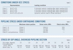
The ambient temperature is 5° C., the pipe operating temperature is 38° C., and the operating pressure is 10 MPa. Stress analysis of seismic conditions mainly involves the weight of pipeline and its transported medium, W, operating pressure, P1, operating temperature, T3, and dynamic seismic load stress D. D1 is the dynamic seismic load in X direction. D2 is the dynamic seismic load in Y direction. And D3 is the dynamic seismic load in Z direction.
Table 2 lists the load and seismic conditions.
Model building
Analyzing pipeline stress in an earthquake requires establishing these models:
• Fixed pier model.
• Pipe rack and elbow model.
• Soil cover model.
• Straight pipeline section model.
• Integral pipe model.
This approach uses node numbers to mark the pipe pier and elbow. It also uses input load component data and directly attaches a point-stress value to each gas pipeline node.
This article only considers pipeline stress caused by a seismic wave when the tunnel doesn't collapse. Table 3 shows the stress condition of the pipeline under earthquake conditions. The check value of primary stress in the embedded section is 499.5 MPa. The value in non-embedded sections is 416.3 MPa, and the check value of accidental load stress under seismic conditions is 555 MPa. Stress ratio is the ratio of the stress value to the standard value of the stress check.
The horizontal seismic action is obviously stronger than the vertical action (Table 3). Under seismic load in X and Y directions the maximum stress position is Elbow 1. Under seismic load in Z direction the maximum stress position is Elbow 2. Elbow 1, however, is more dangerous when under seismic load in all three directions.
Stress influence analysis
In addition to the pipe pressure and temperature load, changes to basic design parameters of the pipeline may also affect stress distribution.
Changing the incline angle of both the overhead pipe section and the buried section allows analysis of variation in the comprehensive stress and stress ratio of the pipe. The angle range of the pier overhead section is 20°< α ≤ 35°. The range for the buried section is 0° < β ≤20°.
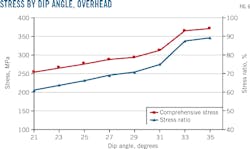
Caesar II software established the inclined pipe model with different angles. Table 4 and Fig. 6 show the maximum comprehensive stresses, stress ratios, and variation trends. The check value of primary stress for the non-embedded section is 416.3 MPa.
The maximum comprehensive stress and stress ratio of the pipeline increase with the larger dip angle of the inclined pipe section (Table 2, Fig. 6). The stress value and stress ratio increased significantly at a dip angle range of 30-35°. The stress ratio reached 89.3% when the dip angle got to 35°. Pipe dip angle greatly influences stress in the overhead pipeline section.
According to the relevant regulations in CDP-G-PC-CR-005-2009/B, when the tunnel slope exceeds 35°, slag-removal capacity drops and negatively affects construction. It is therefore necessary to control the dip angle of the overhead section.
There are two sections of the buried pipeline in the tunnel. The 540-m dip angle is 7.43°and the 600-m dip angle is 6.17°. The difference in dip angle is small and the angle of the elbow is small, allowing analysis of the two sections of buried pipe as a single unit.
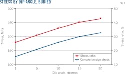
Caesar II software established the model for evaluating inclined pipe with different angles in the buried section. Table 5 and Fig. 7 show the maximum comprehensive stresses, stress ratios, and variation trends. The check value of primary stress for the embedded section is 499.5 MPa.
With the increased pipe-section dip angle, the maximum comprehensive stress and stress ratio of the pipe in its buried section increase at a nearly linear rate, but the stress ratio is not large. The pipeline covered with soil is more than 1,000 m long and the greater the dip angle the easier the soil falls. The pipe dip angle in buried section, therefore, should generally not be more than 20° and a retaining wall should be built.
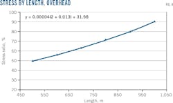
Caesar II software next established a model for overhead pipes of different length, analyzing the corresponding maximum comprehensive stresses and stress ratios (Table 6 and Fig.8). The overhead method is only suitable for short distances, so pipeline length examined was 500-1,000 m.
Fig. 8 shows that with longer inclined tube length in the overhead section the pipe stress ratio increases sharply. The stress ratio reaches 90.23% when the length of overhead pipeline is 1,000m.
The formula for calculating the overhead section's theoretical limit length (l) is obtained via linear fitting: y=0.00004l2+0.013l+31.98. The theoretical limit length (l) for the inclined tube is 1,151.56 m when the stress ratio reaches 100% (y=100%).
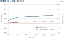
Table 7 shows maximum comprehensive stress and stress ratio for different inclined tube length models in the buried section. Fig. 9 shows the variation trend of stress and stress ratio with the length of inclined tube. The soil-cover laying method is suitable for tunnels of 1,000-2,000 m.
As can be seen in Fig. 9, the increase of inclined tube length in the buried section increases maximum comprehensive stress only slightly and pipe stress ratio is almost unchanged. Length of the inclined tube in the buried section has little influence on pipe stress.
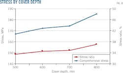
Table 8 and Fig. 10 show the maximum comprehensive stress, stress ratio, and variation trend of pipelines with different covering depths. In the tunnel, the covering depth of pipe in the buried section is more than 500 mm but less than 1 m. The check value of primary stress for the embedded section is 499.5 MPa.
With the increased covering the maximum comprehensive stress of the pipe increases but the stress ratio changes little. Covering depth has little influence on the pipe stress. Even so, covering depth in the tunnel should not be less than 500 mm.7 The construction height of the tunnel and other factors, however, also need to be considered.
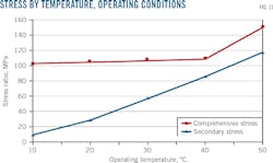
The pipeline model discussed earlier had an installation temperature of 5° C. and design pressure of 10 MPa. Changes in operating temperature mainly affect pipe stress under operating conditions and accidental load conditions combined with operating conditions. Table 9 and Fig. 11 show the variation trend of pipe stress under different operating temperatures.
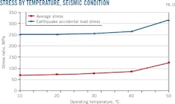
Table 10 and Fig. 12 show the variation trend of pipe stress according to temperature under seismic conditions, the secondary stress growing under operating conditions due to the change in temperature, and increased thermal stress caused by expansion and contraction of the pipeline. The higher the temperature, the greater the thermal stress. Maximum stress occurs at Elbow 2.
When the pipeline's operating temperature is less than 40° C. an increase has little effect on stress, when more than 40° C. attention needs to be paid to temperature increases.
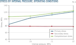
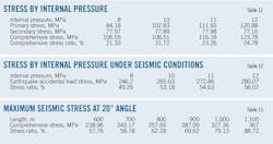
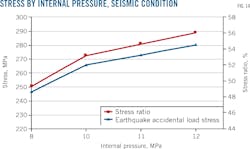
Table 11 and Fig. 13 show the effects of pressure changes on pipe stress under operating conditions. Table 12 and Fig. 14 due the same under an earthquake accidental load stress. The check value of primary stress for the embedded section is 499.5 MPa.
When temperature is constant, primary stress increases with rising internal pressure (Fig. 13). This is because the primary stress is generated by an external load, such as gravity and pressure. When the internal pressure of the pipeline changes, the primary stress will change. When the temperature does not change the change to internal pressure has little effect on secondary stress.
Accidental stress under seismic conditions, however, shows linear growth under constant temperature and increasing internal pressure (Fig. 14). Maximum stress occurs at Elbow 1.
The summary of the influence law of these factors on stress shows that the length and dip angle of the overhead pipeline and its operating temperature and pressure have a great influence on stress through the seismic zone. The length, dip angle, and covering depth of the buried pipeline, however, have little influence.
Dip angle vs. limit length
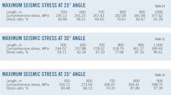
The dip angle of the overhead pipeline in the tunnel is 20° ≤ α ≤ 35°. The length of the inclined tube in the overhead section is 500 m, with 100-m increments added to determine the corresponding relationship between the limit length and stress ratio of the overhead pipeline with different dip angles. Tables 13-16 show the maximum earthquake accidental load stress and stress ratio of the pipeline for varying dip angles and tube lengths. The check value of primary stress for the non-embedded section is 416.3 MPa.
Equation 2 fits the functional relationship between stress ratio and the length of overhead pipeline at a dip angle of 20° as shown in Table 13. The limit length of overhead pipe is 1,186.31 m.
Equation 3 fits the functional relationship between stress ratio and the length of overhead pipeline at a dip angle of 25° as shown in Table 14. The limit length of overhead pipe is 1,100.20 m.
Equation 4 fits the functional relationship between stress ratio and the length of overhead pipeline at a dip angle of 30° as shown in Table 15. The limit length of overhead pipe is 1,034.51 m.
Equation 5 fits the functional relationship between stress ratio and the length of overhead pipeline at a dip angle of 35° as shown in Table 16. The limit length of overhead pipe is 909.94 m.
Equation 6 shows the functional relationship between the theoretical limit length of the overhead pipeline and the dip angle. With increased dip angle the limit length the of overhead pipeline decreases gradually. Safe operation, therefore, requires minimizing the lay angle.
Acknowledgment
This work was supported by the State Special Project of the Fifth Five-Year Plan "Test, Evaluation and Safety Techniques of Oil & Gas Long-distance Pipeline and Storage & Handling Facilities" (2016YFC0802100) and the Consultant and Research Projects of Chinese Academy of Engineering "Strategic Research of the Safety Development of Oil & Gas Pipeline Network" (2015-XZ-37).
References
1. ASME B31.8-2014 "Gas transmission and distribution piping systems," American Society of Mechanical Engineering Press, New York, 2014.
2. Li, J.Q., "Differences and similarities of ASME B31.1 and B31.3 on Criterion to Piping Stresses," Process Equipment & Piping, Vol. 47, No. 5, September-October 2010, pp. 47-50.
3. Wu, X.N., Lu H.F., Huang K., Tang, X.Y., Wu, S.J., Shen, G.Y., and Fu, H.P., "Stress analysis of gas pipelines at seismic belts based on the spectrum analysis," Natural Gas Industry, Vol. 35, No. 5, May 2014, pp. 152-157.
4. Feng, J.Y., "Comparison of pipe-soil interaction model base on CAESAR II," Liaoning Chemical Industry, Vol. 44, No. 7, July 2015, pp. 887-890.
5. "ASME Guidelines for the design of buried steel pipe," American Society of Mechanical Engineers Press, New York, 2001.
6. Zhang, X.L, Li, Y.J., and Yang, X.G., "The design and analysis of the pipeline through the tunnel," Oil and Gas Field Surface Engineering, Vol. 30, No. 4, April 2011, pp. 55-56.
The authors
Yan Xia ([email protected]) is a postgraduate student at Southwest Petroleum University, Chengdu, China.
Chen Liqiong ([email protected]) is a professor at Southwest Petroleum University, Chengdu, China. She holds a postdoctoral degree from Southwest Petroleum University.
Xiaoyu Han ([email protected]) is a teacher at Beijing Institute of Technology. She holds a postgraduate degree from Southwest Petroleum University.
