Trial trimming LNG carriers lifts efficiency, drops emissions
Maksym Kulitsa
FSRU consultant
Odessa, Ukraine
David A. Wood
DWA Energy Ltd.
Lincoln, UK
Simple to implement trial-trimming optimization can increase a ship’s speed at set power consumption by 0.5-1.5 knots (or more) depending on prevailing conditions and ship type, improving commercial performance and reducing emissions.
The effect of trim on ship’s speed is recognized in marine regulations. But implementation of effective measures to assure optimized trim and avoid inefficiency is not yet widely practiced among LNG carrier (LNGC) fleets. Some operators have invested in special systems for trim management and optimization requiring that LNGC be fitted with specialized monitoring equipment on the underwater portion of the hull.
Trial trimming can effectively achieve optimized trim without specialized software or additional monitors and works well with the equipment typically installed on both modern LNGC and oil tankers. LNGC have a trim indicator that requires no underwater hull installation and provides the information required for implementing trial trimming for a wide range of marine conditions and ship speeds. Initial trial trimming trials justify more extensive sea trialing of the method in LNGC and tanker fleets.
Background
LNGC design continues to evolve, with more efficient and effective propulsion, engines, and hull shapes allowing consumption of less fuel for the same distance travelled. These objectives are driven not only by commercial interests but also by regulations aimed at emissions reduction. The mandatory Ship Energy Efficiency Management Plan (SEEMP), European Union monitoring, reporting, and verification (MRV) of CO2; data (which became mandatory Jan. 1, 2018), and the International Maritime Organization data collection system (DCS) addressing fuel consumption (effective Jan. 1, 2019) all are intended to reduce shipping greenhouse gas emissions and fuel consumption.
Addressing these issues generally requires new ship designs, developed in parallel with substantial capital investment to conduct research and testing of potentially more efficient systems at operational scale. This article, however, identifies a real-time, simple operational technique to improve ships’ performance in relation to speed, fuel consumption, and emissions which can be used at no cost and without modifying existing ships’ hull and propulsion designs. The method involves meticulous operational tuning to achieve maximum efficiency at any given combination of hull shape, vessel speed, draft, and weather conditions. Even in the worst combination of these factors, there are settings at which speed reaches its maximum possible value. The trial-trimming technique establishes those settings in an empirical way and is consistent with SEEMP for the majority of existing ships.
Requiring no capital investment, trial trimming can typically increase ship speeds by 0.5-1.0 knots (or more at specified conditions), compared with the inefficient LNGC trims typically employed. The influence of a vessel’s operational trim on fuel consumption and emission is often underestimated.
Commercial software is available to help optimize trim settings. These consider a range of operational and vessel-design inputs to define the optimum trim for a vessel under the typical range of operational conditions encountered. But trial trimming can achieve optimum hull-propulsion performance for any operating conditions by establishing the maximum achievable speed for the conditions prevalent at any given time. It can also be easily reevaluated as conditions change during a voyage (i.e., different depth, pitching due to sea state, etc.). The method is not only applicable in fair seas, but also in moderate and rough conditions.
The average good trim established for prevailing rough sea states, in which pitching frequently causes the bulb to emerge and submerse relative to the water line, can upset general trim effects. But the trial-trimming method still provides a good average speed in such conditions. In case of swell direction or wave height changes, revised suitable average trim settings can be recalculated by trial trimming to achieve good average speed as required.
Many ships follow the somewhat dated empirical rule-of-thumb of setting static trim at between 0 and 0.5 m by stern for each voyage, regardless of the prevailing conditions. Trim by bow is not traditionally considered. Also, the effects of dynamic trim during sailing are typically disregarded. The empirical observations made on a typical 165,000-cu m LNGC make it clear that no one trim setting should be routinely used as the ideal trim for a specific vessel. Optimal trim setting depends on many factors including ship design, prevailing loading condition, speed constraints, depth of water, sea state, etc.
Trial trimming has been verified on a membrane LNGC with a common hull shape, size, and dual-fuel diesel-electric (DFDE) propulsion system. Empirical observations made it possible to find the optimum dynamic trim at any given conditions for that LNGC. Subject to further testing, the method provisionally appears to be suitable for the majority of commercial ships (particularly LNGC and tankers) with common hull forms and bulbous bows.
The effects of dynamic trim tend to be underestimated on ships for which special trim optimization systems are not installed. Dynamic trim calculations are complex, making it simpler to measure directly rather than calculate. The difference between static and dynamic trims can be substantial. Using dynamic trim analysis can change hull responses during sailing compared with static trim expectations. Typically, a ship departs on an even keel but its dynamic trim often shifts towards the bow by magnitudes that depend on the ship’s speed. Thus, with an expected even-keel hull response from static trim, the ship hull’s actual response is determined by a different dynamic trim value, as the ship moves at its planned voyage speed.
Ship-speed optimization
Achieving and maintaining an optimal trim throughout any ship’s voyage can improve fuel efficiency by up to about 6%. IMO SEEMP states: “Most ships are designed to carry a designated amount of cargo at a certain speed for a certain fuel consumption. This implies the specification of set trim conditions. Loaded or unloaded, trim has a significant influence on the resistance of the ship through the water and optimizing trim can deliver significant fuel savings. For any given draft there is a trim condition that gives minimum resistance. In some ships, it is possible to assess optimum trim conditions for fuel efficiency continuously.”
The reference to “some ships” in this quote refers to those specifically using trim-optimization software, equipment linked to special sensors fitted to their hulls. This provision, however, can be applied by simply monitoring and responding to a few parameters that are usually available on modern ships without recourse to costly sensors. These parameters can be used to identify the ideal trim to minimize fuel consumption for given speed, cargo-loading conditions, and location.
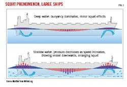
The term “sinkage” refers to the increase of a ship’s draft moving through water. A ship always has a dynamic draft that is generally deeper than its static draft, and a dynamic trimming effect while moving through water (Fig. 1). These dynamic values change as a vessel’s speed increases. Sinkage is often referred to as “squat” in shallow waters (Fig. 2). Dynamic trim evolves from static trim depending on hull form, loading conditions, and a ship’s speed through the water. Depending on the forms of a ship’s bow and stern, in the majority cases, water inflow has an apparent downward pull at the bow and upward push at the stern, due to the stern’s flare. Empirical observations reveal that a modern LNGC is always likely to be dynamically trimmed towards the bow from any initial static-stern trim. But this effect may vary depending on specific hull design.
The bulbous bow, present on almost all ships, is designed to reduce wave formation at the bow and convert the avoided wave-making energy into speed. However, the typical ship’s bulb is designed to be effective at certain loading drafts, commonly at even keel, and for a specified operational speed. Consequently, they are typically not designed for LNGCs during ballast voyages. For such ships and voyages, the bulb usually emerges out from the water and enhances rather than reduces wave formation. Bulbs achieve maximum efficiency at specific submergence and ship’s speed. For that reason, vessel trim has an indirect influence on bulb efficiency. The trial-trimming method can find an optimal trim for ballast voyages by keeping bulb efficiency and hull resistance in optimal balance. This achieves optimal vessel speed for the prevailing specific speed and environmental conditions.
Modern bulb designs exist that minimize inefficiency during ballast voyage conditions, but not many vessels with these designs are operational. New bulb designs appear to perform well during both loaded and ballast voyages.
The trial-trimming technique, however, can even potentially improve fuel efficiency for LNGCs with the latest bulb designs. The correct position of the bulbous bow is under the surface during all sailing conditions. Ideally, the bulb should not emerge above the water, nor should it be too deeply immersed below the water surface. Too much bulb immersion does not produce any effect in reducing the bow wave.
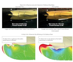
In theory, the wave generated by the bulb itself should diminish the hull bow wave (Fig. 3). When operating most efficiently, the ship’s operator should not see any large wave on the bow area. However, bulbs tend not to be effective at low speeds, and can even have negative outcomes in such conditions. Bulb efficiencies tend to increase as a ship’s speed increases.
For any given draft and speed, there is a trim condition that gives minimum total-hull resistance. Therefore, any ship’s optimum trim is a direct function of its draft and speed. This means that whatever the condition of a ship, there will always be a point at which the ship will display its hull’s lowest total resistance possible while passing through the water. Optimum dynamic trim can be defined as the trim angle at any particular displacement and speed at which the propulsion power used is lower than the propulsion power used for any other trim angle at the same displacement and speed. Operating the vessel at its optimum dynamic trim can result in the vessel sailing at a higher speed or lower propelling power. Optimizing trim therefore provides cost savings with respect to fuel consumption and reduces emissions.
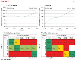
Finite difference simulations reveal that optimal trim constantly varies, lying somewhere between trim by stern and trim by bow. The exact ideal trim varies for the same ship according to its speed and draft (Fig. 2). For most ships, simulations and empirical observations suggest that it is better to sail at minimum draft and slightly trimmed by bow to the maximum extent practically attainable. But this rule is not universal and depends on hull design. Even so, optimum trim is more meaningfully expressed in terms of dynamic trim measurements than static trim measurements.
Optimal dynamic trim is often not achieved at all throughout a typical LNGC voyage, as operators underestimate its value. Typically, trim-by-stern or even-keel constraints are applied. On the other hand, from fuel consumption perspectives, optimal trim is a value that ideally needs to be maintained within quite narrow limits. A trim deviation of just 25 cm can have a significant impact on fuel efficiency. LNGC-operating experience suggests that trim by bow should not be disregarded, as in many cases it is found to be beneficial for fuel saving (Fig. 2).
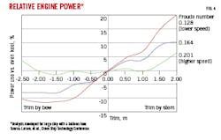
Figs. 4-5 show the variation of propulsive power as a function of trim and vessel speed represented by the Froude number. Trimming some ship designs by bow appears to be beneficial at lower speeds. As speed increases, optimal trim gradually moves closer to even keel (zero trim in Fig. 4).
Defining optimal dynamic trim
There are two ways to optimize a ship’s trim. The first is to purchase software requiring specialist sensors be fitted to the ship’s hull. This requires the installation of additional draft gauges designed to provide dynamic draft measurements. Typically, ships are only fitted with static draft gauges that display inaccurate values during sailing. The information gathered should reveal to a ship’s operator whether a ship is optimally trimmed or not at each stage of a voyage.
The second way is to approach the issue from the ultimate objective: to establish the maximum attainable speed that can be practically achieved under prevailing conditions. That maximum attainable speed is for a given engine power and will vary depending on many real-time factors, including weather, ship-loading conditions, etc.
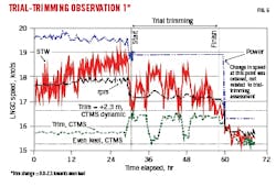
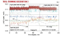
Empirical observations (Figs. 6-7) recorded for a DFDE LNGC are ideal for such evaluations as power is typically kept constant by generators. Dynamic trim information was recorded using the custody transfer measurement system (CTMS) with the Kalman filter option applied. Also, the integrated automation system (IAS) recorded engine revolution, thrust, torque, speed through water, and speed-over-ground trends.
Figs. 6 and 7 show that the LNGC’s speed through water increased as trim decreased towards even keel. Unfortunately, there were no data available to determine how much the LNGC’s speed would have increased further if trim-by-bow conditions had been implemented. The recordings were for a ballast voyage with bulb not effectively submerged due to the imposed rule-of-thumb to only trim by stern. Even on an even keel the bulb was visibly ineffective and breaking out, with small waves created (Fig. 2).
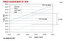
Fig. 8 summarizes a trim optimization case study for a typical LNGC performed using DNV GL ECO Assistant software. At higher speeds, the optimum trim is estimated to be 1.0 m by bow. For slower speeds, the optimum trim is estimated to be 1.5 m by stern. These estimates suggest that the LNGC should implement trim-by-bow conditions to achieve minimum fuel consumption for most of its open sea voyage.
Trial trimming
Trial trimming is easy to implement as an operational measure focused on maximizing vessel speed and minimizing fuel consumption and emissions for a specific engine power. The final objective is to achieve the highest speed for the same engine power (fuel consumed). Trial trimming involves zero capital cost as only operational monitoring measures and ballast movements are required. Measures are easy to implement on any LNGC, which are all fitted with the equipment needed to make the required measurements.
To achieve maximum efficiency, some related operational procedures need to be established and acted upon. These procedures account for the following principles:
- A ship has less resistance (friction) with a smaller wetted area of the hull, achieved by minimizing the average vessel draft as much as practically possible.
- Ship’s propeller should always be completely immersed in water with some margin.
- Bow bulb should always be carefully positioned just below the water surface (verified by visual observation).
- Trim indicator (CTMS on tankers) system shows consistent dynamic trim values during sailing.
Taking these principles into consideration, the loading-ballast condition of the ship and its associated average draft can be feasibly planned to some extent.
Tests can be conducted with a ship sailing at a constant speed and steady course to find the optimum trim. The LNGC’s trim can be adjusted incrementally in small steps through a range of settings from about 2.0 m trim by stern through to 2.0 m by bow, if hull strength allows, during a relatively short period. This assures trial trimming during relatively constant weather conditions, minimizing weather-related effects on speed.
The ship’s speed is allowed to stabilize over a period of about 30-60 min at each trim setting and the stable speed through water (STW = log speed) recorded. These trends (Figs. 6 and 7) reveal the trim setting at which maximum speed through water was achieved. That trim should then be adopted as the optimal dynamic trim for the prevailing conditions, vessel’s present speed, water depth, and loading condition (i.e., draft). Ideally, such trim-trial observations should be conducted in calm or fair weather. But trim trials can be performed in moderate-to-rough seas to find a suitable trim setting for an average maximum attainable speed in unfavorable conditions.
Trim-trial observations are best conducted using an LNGC’s fore-peak and aft-peak ballast tanks. Hull seagoing strengths normally will allow trimming using these tanks. As part of trim trials, three visual observations and assessments should be made and noted:
- Position of the bulb in relation to the water level and its optimum position.
- Wave formation around the bow area (Fig. 3).
- Confirmation that the propeller is fully immersed.
There are some additional factors that need to be considered when conducting trim-trial observations. Shallow water affects dynamic trimming and speed. Ships tend to experience shallow water impacts once water depths become less than six times a vessel’s draft. Consequently, for large ships such as LNGC, significant shallow-water resistance impacts are experienced at depths less than 30 to 50 m and these will naturally affect the optimum trim settings. For a ship coming from deep waters into shallow waters, or vice versa, for prolonged duration at sea before arriving at port, or where a ship’s speed changes significantly, then trim-trial observations should be repeated for the new conditions.
For ballast-voyage conditions on LNGC, empirical observations indicate that dynamic trim-by-bow settings likely are required to submerge the bulb correctly while maintaining minimum vessel draft and a fully submerged prop. For loaded-voyage LNGC conditions, it is likely that dynamic trim-by-stern settings are required to avoid immersing the bulb too deeply during dynamic trimming at typical ocean-going speeds.
This simple method can be implemented in five steps:
- Establish a ship at the rough planned sea speed (±1 knot) expected once its sea passage has commenced.
- Conduct trim-trial observations for the ship with fore-peak and aft-peak ballast movements over a dynamic trim range of about 2 m (if possible) by bow and by stern, on the same course.
- From the recorded STW log-speed trends over the dynamic trim-range tested, identify optimal trim for the conditions (i.e., the trim at which STW log speed peaked). Return to this optimal trim.
- Adjust engine rpm to attain the required planned voyage speed.
- Re-record trim-trial measurements when water depth changes substantially (shallow to deep, or vice versa), or when the ship’s speed needs to be changed markedly for operational reasons or significant sea-state changes.
Applying trial trimming on non-tankers would require they be fitted with a cheap and simple gravity-type trim indicator, a monitoring system used in the CTMS fitted on tankers that incorporates a Kalman filter option for processing its readings to minimize the influence of noise. Such a solution is substantially cheaper than installing specialist trim-management systems and their required software and hardware while providing fit-for-purpose trim optimization. The increased operating efficiency trial trimming achieves is likely a motivational factor for companies to apply it widely as part of SEEMP.
Bibliography
DNV-GL, ECO Assistant 4.1, 2017.
DNV-GL, EU MRV and IMO DCS, 2019.
Force Technology, “Trim optimization - an efficient tool for minimizing energy consumption,” 2019.
ICS-Shipping, “European Union Monitoring, reporting and verification (EU MRV) regulation,” International Chamber of Shipping Guidance, 2015.
Larsen L. N., Simonsen C.D., Klimt Nielsen, C., and Råe Holm, C., “Understanding the physics of trim,” Ninth Annual Green Ship Technology Conference, Copenhagen, Mar. 27-29, 2012.
Marine Environment Protection Committee, “Guidelines for the development of a ship energy efficiency management plan (SEEMP), Resolution MEPC.282(70), adopted Oct. 28, 2016.
Reichel, M., Minchev, A., and Larsen, N.L., “Trim optimisation - theory and practice,” TransNav - The International Journal on Marine Navigation and Safety of Sea Transportation, Vol. 8, No. 3, September 2014, pp. 387-392.
The authors
Maksym Kulitsa ([email protected]) is an FSRU on-board operator with more than 8 years’ experience of different regas systems on different FSRU terminals. Since FSRU is a relatively new direction in LNG industry, Maksym took a private interest and initiative in optimizing FSRU-related operations to achieve its best efficiency as particular ship designs and operating conditions allow.
David A. Wood ([email protected]) is principal consultant of DWA Energy Ltd, UK. He has more than 40 years of international oil and gas experience spanning project operations, technical evaluations, research, contract negotiations, senior corporate management, and expert witness services.
