Cutting feed-gas lines to plant as production slows limits slugging
Taib Abang
Muhammad Rizwan Tariq
Mohammed Abbas Khuraidah
Saudi Aramco
Dhahran
Reducing the number of feed gas pipelines delivering raw natural gas to processing plants as volumes fall can reduce slugging and the volume of liquids transferred downstream while maintaining gas delivery volumes. The typical inlet at gas plants receives raw feed gas with associated hydrocarbon condensate and water from multiple wells.
The first equipment in the inlet area is a slug catcher, which separates the bulk of the water and hydrocarbon condensate from the gas phase. The separated hydrocarbon condensate is stabilized to achieve the required true vapor pressure (TVP) and then injected into the neat condensate line. Water separated from the slug catchers is diverted to sour water stripper (SWS) trains. The overhead acid gas from the SWS trains is routed to the sulfur recovery unit (SRU), and stripped sour water is sent to the evaporation ponds. The separated gas from slug catchers and three-phase separators is sent to gas sweetening and dehydration trains.
Slugging
Slugging can occur in a multiphase pipeline due to either hydrodynamic, terrain-induced variables, or transient change in an upstream operating condition. The cyclic unsteady flow characterized by large amplitude, relatively long-period pressure and flow rate fluctuations is known as slug flow.
At a low feed-gas flow rate, liquid accumulates at the low points of the pipeline, blocking the gas, until sufficient upstream pressure has built to surge the liquid slug out of the pipeline, followed by a gas surge. After a fluid and gas surge, part of the liquid in the pipeline falls back to the low points of the pipeline to create a new blockage, and the cycle repeats. This transient cyclic phenomenon causes a period of no liquid and gas production at the pipeline endpoint followed by very high liquid and gas surges and is called severe slugging.
In a typical slug-catcher control arrangement, raw feed-gas enters the slug catcher and the water is separated by gravity separation and eventually ends up in the boot. Hydrocarbon condensate is removed from the bottom, and wet gas from the top, of the slug catcher.
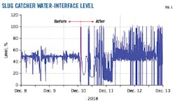
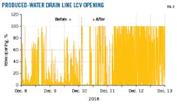
During a slugging incident, the interface level in the slug catcher suffered severe fluctuations and the level control valve (LCV) on the water drain line was 100% open (Figs. 1-2). The vessel’s water interface level was stable at 40-60% until Dec. 10, 2018, and then started to fluctuate, reaching 100% with the LCV opening also at 100%, indicating there was a slug volume in the slug catcher higher than the vessel’s water handling capacity. To avoid water carryover with the condensate stream, the LCV’s manual bypass valve was opened. The slug continued cycling every 10-15 min.
Slugging caused continuous fluctuation in the water interface level, which severely impacted the proper separation of water and hydrocarbon condensate in the slug catcher. This resulted in high water carryover with the condensate stream to downstream processing.
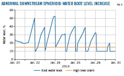
Downstream units received an abnormally large slug of water, draining almost five times more than normal (Fig. 3). The downstream plant was not designed to dehydrate incoming streams and could receive no more than 0.2% of basic sediment and water (BS&W). The need to conduct manual draining once the interface level reached 50% required a large amount of time. The alarm was activated at 15% and the normal level is 10%.
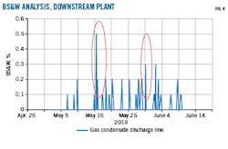
BS&W spot checks at the downstream gas condensate discharge line showed general compliance with BS&W specifications, below 0.2% (Fig. 4). Fig. 4 also shows that downstream condensate BS&W increased to 0.5% for a few days. This high water-content in the condensate has the potential to accumulate water in the product pipeline, which can also contribute to high water reaching the downstream plant.
Salt fouling
High water carryover with condensate to the condensate stabilizer caused salt fouling in the stabilizer reboilers. There were frequent startups and shutdowns on condensate stabilizer equipment, mainly to manage salt fouling at the stabilizers’ reboilers. This mode of operation disturbed the condensate network and downstream units.
The root cause of salt fouling was the reboiler tube surface’s high temperature, which was well above saltdeposition temperature. This high reboiler temperature resulted from high boiling-point heavy hydrocarbon components traveling with the free water to the condensate stabilizer. High-salinity water in the condensate combined with the high reboiler temperature to vaporize the water, leaving salt on the surface of the reboiler tubes.
The salt fouling at the gas plant resulted in operating problems:
- Increased energy consumption due to salt accumulation in the stabilizer’s reboilers.
- Higher maintenance costs due to increased cleaning frequency and chemical cleaning.
- Frequent startups and shutdowns, resulting in increased flaring.
Water accumulation
Water carryover from the slug catcher to the downstream condensate stabilization unit caused water to enter the downstream pipeline along with the treated condensate. It then accumulated in low points of the pipeline.
Production loss
Extremely high water-carryover from the gas plant, combined with water accumulation in the pipeline, resulted in high water in downstream storage tanks. This high water-level then would require interrupting downstream production to avoid making off-spec product.
During high fluctuations in the water interface level of the slug catcher, condensate can carry under with the sour water the water sent to the downstream stripper. Hydrocarbons in sour water feeding the stripper can increase the risk of serious fouling of the stripper’s internals and reboiler, and of the bottom section of the tower.
Suspended solids in the sour water feed are common. To some extent, these will settle in the upstream feed stabilization tanks. A considerable portion also will be contained in the outlet water. The effects of suspended solids can be like those of hydrocarbons, as they will deposit on metal surfaces leading to ineffective flows and under-deposit corrosion. The presence of hydrocarbons and suspended solids together exacerbates their effects as the suspended solids will agglomerate with certain hydrocarbons, generating a highly fouling material.
This deposition can cause reduced stripping efficiency, corrosion, and excessive maintenance costs. The pH of the sour water has a direct relationship with the solubility of hydrocarbons in water; the higher the pH, the higher the solubility.
Once hydrocarbons enter the stripper, they can either vaporize and travel upward with the steam or stay in liquid form and travel downward with the water. Neither direction is desirable. But given the choice, it is better they vaporize and can then possibly be condensed in the reflux or pump -around system. Either option, however, creates both operational and mechanical problems in the SRU.
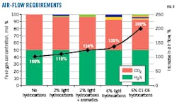
SWS acid gas containing more than 2% hydrocarbon is a firm indication of problems upstream of the stripper. Hydrocarbons consume large amounts of oxygen in the reaction furnace, affecting the H2S:SO2 ratio in the SRU (Fig. 5). Hydrocarbons in the acid gas transferred from SWS to SRU also can cause unstable operation, which could lead to catalyst soothing, deactivation, or fragmentation, and off-spec sulfur product from the SRU.
Process analysis
Liquid accumulation in two feed gas pipelines was identified as one of the major causes of slugging in this system. Multiphase simulation was conducted for one pipeline to determine the minimum and maximum flow rate that the pipeline should maintain to minimize liquid hold-up.
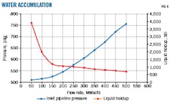
Fig. 6 shows the total liquid hold-up and required pipeline-inlet back pressure at the launcher for different flow rates. At flow rate less than 150 MMscfd the liquid hold-up in the pipeline increases significantly.
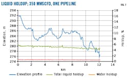
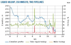
Figs. 7 and 8 compare liquid hold-up when operating one pipeline versus two at a total flow rate of 350 MMscfd. Lower water hold-up (0.61%) was observed when operating one pipeline, while liquid hold- up was higher (1.0%) when operating two pipelines at 175 MMscfd.
Simulator analysis yielded the following:
- Liquid hold-up increases significantly when operating below 150 MMscfd.
- A single pipeline can accommodate a flow rate of 350-430 MMscfd at pipeline-inlet back pressure between 640-700 psig.
- At a flow rate less than 260 MMscfd, a slug-flow regime is expected along the pipeline (Fig. 4), as compared with a flow rate greater than 260 MMscfd, under which the flow regime is stratified wavy for the entire pipeline.
- At a flow rate of 270 MMscfd, the gas superficial velocity is at 32 ft/sec (10 m/sec), the maximum velocity allowed by Saudi Aramco Standards.
These findings were later confirmed by the plant running one pipeline at higher flow, which helped avoid slugging because of less liquid hold-up.
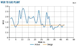
A high water-gas ratio (WGR) in feed gas to the inlet-area slug catcher can be another reason for liquid carryover to downstream. Reference data for feed gas and water flow rates show that inlet slug catchers received higher WGR than design (Fig. 9). This can cause poor liquid-liquid separation in slug catchers and liquid to reach downstream units.
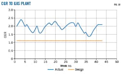
Higher condensate-gas ratio (CGR) can also contribute to water carryover when it reduces residence time below that needed for good liquid-liquid separation (Fig. 10).
Mitigation
Major mitigation actions to avoid slugging include:
- Understanding the upstream system by obtaining data needed for analysis to confirm whether there is slugging or not.
- Operating a single feed-gas pipeline once the gas rate is below the minimum recommended flow rate.
- Producing feed gas from lower CGR and WGR wells, when possible, to limit the liquid volumes that reach the slug catchers.
Bibliography
- Al-Helal, E.F., Mankour, Y., Al-Boobaid, M.J., Al-Jeshi, M.A., Tariq, M.R., Khuraidah, M., and Abang, T., “High water content in gas condensate at refinery,” Saudi Aramco Engineering Report SAER-9073, May 2018.
- Abang, T., Al-Boobaid, M.J., Saati, M.Y., Al-Jeshi, M.A., and Davis, I., “Salt fouling in Condensate Stabilizer Reboilers at Gas Plants,” Saudi Aramco Engineering Report SAER-9071, July 2018.
- Spooner, B., Derakhshan, F., and Engel, D., “Measures to minimize the level of hydrocarbons in sour water and thereby protect the efficiency of the sulphur plant,” Nexo Solutions, 2016.
The authors
Taib Abang ([email protected]) is an engineering specialist at process and control systems department, Saudi Aramco, Dhahran, Saudi Arabia. He has also served as a senior engineer at Petronas LNG, Malaysia. He holds a Bachelor of Engineering (Chemical) earning in 1995 from University Malaya, Kuala Lumpur, Malaysia. He is a chartered engineer from Engineering Council and chartered member of IChemE UK.
Muhammad Rizwan Tariq ([email protected]) is a senior process engineer at process and control systems department, Saudi Aramco, Dhahran. He has also served as a staff or senior engineer at JGC Corp., Worley Oman Engineering LLC, Petroleum Development Oman, and Oil and Gas Development Co. Ltd., Pakistan. He holds a BS in chemical engineering (2000) from Punjab University, Lahore, Pakistan. He is a chartered member of IChemE UK and a professional engineer from PEC Pakistan.
Mohammed Abbas Khuraidah ([email protected]) is a flow-assurance engineer at process and control systems department, Saudi Aramco. He has also served as an operation engineer at Saudi Aramco’s Khurais central processing facility and Northern Area pipelines. He holds a BS in chemical engineering from Wayne State University, Detroit, Mich., and is pursuing a Master of Engineering in oil and gas from the University of Western Australia.