New barrier valve provides option for stacked completions
Alexander Patalakha
Gregory Neal
Shell Exploration
Houston, Tex.
Bryce Randle
Spoked Solutions
Houma, La.
Stacked, non-selective commingled well designs present specific difficulties for zonal isolation and fluid loss-control during their initial construction. Bidirectional isolation valves, which can be opened remotely, are widely utilized to isolate the upper completion from the lower completion, but typically reside only in the uppermost zone of the lower completion. Further isolation between separate or segmented reservoir units within the lower completion typically utilizes less robust, single-direction, temporary isolation devices that are not qualified barriers. In reservoir conditions where differential pressures between hydraulic units are more severe or uncertainty exists, the need for bidirectional pressure isolation becomes more complex, and completion designs become more complicated.
Shell USA Inc. used a jettisonable ball seal (JABS) bidirectional barrier in dual-use producer-injector completions for a water-flood field in the Gulf of Mexico (GOM). The barrier initially isolates zones during selective perforating, then opens by jettisoning the ball after completion. The ball valve successfully operated, with ball jettison observed on real-time pressure charts.
JABS
Shell embarked on a multi-well water-flood campaign to support existing GOM assets. The wells were designed as dual-use producer-injectors and completed as stacked, cased, perforated, and non-selective commingled zones. These well designs used the JABS bidirectional, gas-tight barrier to isolate the lower zone of the lower completion before perforating the upper zone of the lower completion. The operator has utilized this tool previously in both single-zone and stacked selective-completion designs, where it could later be jettisoned hydraulically. This application did not rely on selectivity between reservoir units for a design basis and thus could not provide the ability to hydraulically function as a fluid loss or isolation device with open perforations above it in the upper zone of the lower completion.
Several engineering and operational factors determined the design choices. This application required reservoir segmentation into two discrete units but did not rely on selectivity between reservoir units for a design basis. Thus, the design could not provide the ability to hydraulically function a fluid loss or isolation device between units with open perforations in the upper unit, either during initial construction or later by the host. The vertical extent of the reservoir required perforating long intervals, and the associated dynamic underbalance had to be reduced within equipment operating envelopes while also accommodating potentially large amounts of perforating debris. Further, differential depletion within the reservoir required flexibility to manage potential losses due to pore pressure heterogeneity.
Segmenting the reservoir section to address these issues required JABS to be robust, debris-tolerant, and bidirectional. Hydrostatic and differential pressure ratings needed to meet and possibly exceed 5,000 psi. Other technologies available on the market were limited to about 3,000 psi differential pressure in a single direction. JABS accomplished these objectives during initial construction, enabling the isolation device to be opened without applying surface pump pressure for cycling a J-mandrel or a similar approach, and without the need for a concentric flow path to the device.
GOM application
The water flood campaign consisted of three wells with about 30,000-ft measured depth (MD) in 4,000 ft of water. Other well parameters included maximum inclination angles of 16°, 1,000-ft reservoir sections, bottom hole pressures above 20,000 psi, and temperatures nearing 265° F. Critical success factors related to well performance focused on net reservoir thickness, low skin, initial production expectations, later injection rate projections, and delivering a reliable well completion while maintaining integrity for both the initial production and later injection phases over the well's life.
Several major completion risks for the wells were identified. Long perforation intervals were required to achieve later-life injection targets, and varying differential depletion occurred not only between reservoir layers but also between well locations. Fluid loss in both reservoir segments was a cause for concern and could not be solely managed via changes to fluid densities.
This application deviated from prior usage of the JABS isolation device. Whereas this device was typically opened via hydraulic pressure applied at the surface, this well design required a trapped pressure chamber and piston mechanism between the two units with the chamber pressurized as the assembly stabbed into the polished bore.
The chamber was created by placing a bullnose in the tailpipe below the service tool of the upper zone assembly, accompanied by 3.88-in. OD seals. Once the floating seals entered the polished bore ID of the lower-zone gravel-pack packer with the designed amount of set-down force and travel, the assembly acted as a piston and pressurized the chamber against the exposed surface area of the JABS ball until sufficient force was generated for the shear pins to yield, jettisoning the ball. The floating OD seal exposed a communication port when in the lowest position (pulling out of the hole). This prevented hydraulic lock in case the string had to be picked up.
JABS design
A key component of JABS design included carefully customizing the shear pins to yield under varying well conditions while accommodating subsurface uncertainties. The required set-down forces span a range affected by overall reservoir pressures, fluid density, material temperature derating (deration), as well as dynamic crossflow effects within the reservoir units themselves. Shear-pin yield values target a minimum of 3% error margin with empirical and run histories. They typically show less than 1% error while also accounting for necessary temperature deration. This application customized the JABS shear pins for 3,285 psi, 4,785 psi, and 3,775 psi at 253° F. for Wells #1, #2, and #3, respectively.
As this was the first time attempting this method of jettisoning the JABS ball, other parameters required extensive empirical testing as well as torque and drag analysis to confirm how set-down forces would transfer to the JABS ball to achieve a successful opening. Operational parameters were analyzed to prevent buckling loads on the smaller OD tailpipe.
Other concerns included the potential for shock loading the JABS ball and prematurely jettisoning it during perforation of the upper zone. The design used an isolation plug in the lower-zone gravel pack bore to protect the JABS from perforation shocks and dynamic underbalance effects exerted on the plug, as well as debris generated from perforating.
The project team also needed to decide if its chosen perforation strategy should account for the JABS-pinning design as the JABS would be exposed to the perforating-shock load after closure if the packer plug failed. For each of the three wells, the team elected not to include the perforation load in the pin design, which would have added about 20-kip additional force to the ball. Given some uncertainty regarding the degree of shock load expected from perforating above the JABS, the operational consequences of not jettisoning with piston force due to available weight-on-bit were greater than the risk of a premature opening. Extensive perforation shock modeling excluded those factors in the shear-pin design.
Difficulties in estimating generated forces on the JABS included the combinations of hydrostatic pressure trapped in the piston mechanism once the OD seal engaged the seal bore above the JABS, weight-on-bit driven by the OD seal or JABS ball’s effective cross-sectional area, and the force generated by the momentum of the workstring when landing the seal.
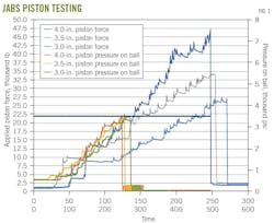
To create the testing scenario, about 500 psi was applied to 4.0-in., 3.5-in., and 3.0-in. internal diameter seal bores to mimic fluid overbalance. All tests utilized a 5.0-in. OD JABS with a 2.4-in. effective ball diameter. JABS custom shear pins are designed and manufactured to fail within 3% of the design and were thus considered constant based on a 3,500-psi design opening pressure for all three tests. With the seal-bore diameters being the only variable, the test fixture included both a force gauge and a pressure gauge to document the mimicked overbalance and the maximum force required to jettison.
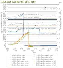
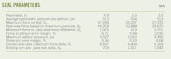
Recorded data for each test and maximum recorded forces for each test are shown in Fig. 1 and Fig. 2, respectively. Table 1 combines recorded data and tests, showing that, for a constant opening pressure, the seal area of the piston provides the required force. The average hydrostatic pressure pre-jettison is equivalent to an overbalance pressure across the JABS ball. The seal area force is the force generated by the ram for each seal size based on the maximum recorded pressure to jettison. The consecutive data maximum represents the maximum force difference recorded at 5 hz between two consecutive data points, and the resting ram pre-, post-test shows the differential stabilized force on the ram pre- and post-jettison.
An unexpected result from the testing was the sensitivity of data acquisition and its effect on interpretation. Calculating the weight on bit based on the seal area and opening pressure alone is not accurate. Once the OD seal is engaged in the seal bore, the trapped overbalance acts equally in all directions (it should no longer be treated as an overbalance due to hydrostatics) and places an upward force on the seal that must be overcome by slacking off. The calculation for determining weight on bit in this scenario is not a static calculation, but instead a dynamic one. String weight, set-down speed, seal-to-ball distance, and fluid volumes combine to provide momentum to the ball, and these are difficult to delineate. Finally, data recording rates (5 hz for this test) are not granular enough to accurately predict or document maximum forces and pressures.
The translation of energy over 30,000 ft of workstring at 2.4 in./sec slack-off speed (example from Well #2) is not practical when less than 0.5 in. of movement will jettison the JABS ball. This means that for every 1,000 lb of force not captured on a gauge, 80-141 psi is applied to the ball relative to the seal size.
Field results
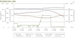
Fig. 3 shows the JABS piston-opening signature for the Phase 2 project. The green line is weight on bit and represents the applied piston force on the ball. The saw-tooth behavior indicates seal drag as the tailpipe enters the seals in the polished bore of the lower-zone gravel-pack packer. Build-up of WOB indicates pressurization of the chamber once it became isolated. Applied piston force begins around the inflection point at ~1:46:40. The ball was jettisoned at about 1:47:45.
This signature was the primary indication for successful jettison with a secondary validation signature comparing pre-jettison and post-jettison fluid-loss rates between the two reservoir units after they were brought into communication once the service-tool seals opened. The learnings from these operations confirmed the validity of utilizing these signatures as indicators of success. Improvement opportunities, however, remain in improving rig data-acquisition systems to improve confirmation and observed data with engineering calculations.
Based on these learnings, the Phase 2 project team recommended minor acceleration of run-in-hole speed to increase force to open the JABS and decrease buckling severity. This mitigation was not a requirement but did reduce the risk of implementing this new technique for barrier valve manipulation.
Authors
Bryce Randle ([email protected]) is an inventor and part owner of Spoked Solutions. He holds a BS in Civil Engineering from Purdue University (1999). His 25 years of experience has primarily focused on sand control in the Gulf of Mexico, Caribbean, and Caspian Sea regions where he was able to implement new technologies and processes both for his employers and Spoked.
Alexander Patalakha ([email protected]) is a lead wells engineer at Shell with 25 years of experience in petroleum and wells engineering. He holds an MS in Petroleum Engineering from the Gubkin State University of Oil & Gas, Moscow (2000). He has experience in West Africa, Western Siberia, the Caspian Sea, Sakhalin Island's sub-arctic region, and the deepwater US Gulf of Mexico, focusing on land, offshore, and subsea field developments, intelligent completions, sand control, well stimulation, coiled tubing and well intervention, and HP/HT and H2S environments.
Gregory Neal ([email protected]) is a wells engineer at Shell with 18 years of experience in completion and intervention engineering. He holds a BS in computer engineering technology from the University of Houston (2005). His career has spanned both land and subsea developments from the Permian basin and Fayetteville shale, to Brazil, but primarily focused on the Gulf of Mexico where he has led multiple projects for Shell. He has extensive experience with well stimulation, coiled tubing, wireline, sand control, well intervention, and completions, and has implemented first-use applications for multiple emerging well technologies.