TECHNOLOGY Irregular tooth spacing reduces roller cone bit tracking problems
John V. Kenner
Hughes Christensen Co.
HoustonTurlach P. Boylan
Transatlantic Technical Services
Houston
On tungsten carbide insert bits, irregularly spaced teeth can help stop tracking problems, leading to increased penetration rates and longer bit runs.
Tracking, which occurs when teeth fall into the craters formed during previous bit rotations, severely affects the performance of roller cone rock bits. The tracking tendencies of tungsten carbide insert (TCI) bits are generally considered once the bit is built and tested, rather than during the design process.
Once tracking is initiated, crater depth quickly reaches the full projection of the teeth, bringing the cone steel in contact with the rock. This tracking increases the contact area while reducing contact stresses beneath the inserts.
Tracking increases the likelihood that neighboring rows of cutters will line up on the hole bottom, forcing the bit to rotate about a point other than its geometric center. This phenomenon is termed off-center rotation or forward whirl. Off-center rotation produces rings of uncut bottom and a further reduction in contact stresses.
This article covers laboratory and field data used in the development and validation of a proprietary algorithm that determines the optimal tooth spacing to eliminate tracking. This study confirms that an algorithm can be applied effectively in the roller cone bit design process to improve coverage of the rock surface during drilling. In addition, these laboratory tests improve the understanding of a single gear-like wheel, a key to understanding total bit behavior.
Recent developments in rolling cutter bit technology have focused on metallurgy, metal-faced bearing seals, roller cone bit dynamics, and high drilling rates in ultrasoft formations.1-4 More recently, a study was undertaken to re-evaluate how the cutter placement of roller cone rock bits can affect rock removal.
Roller cone bits do not operate against a smooth rock surface. The rock surface contains craters and ridges formed by the cutting action of previous bit rotations. Tracking occurs when teeth consistently align with existing craters. Large craters and ridges develop, forcing the bit cones to slip as the teeth index to match the crater pattern.
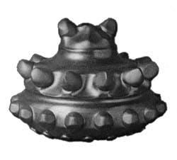
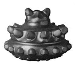
The ridges of an uncut formation quickly reach the full projection of the teeth, resulting in cone steel wear and possible loss of inserts. Tracking is a stable mode of bit behavior recognized by the characteristic sculpting and dimpling of the cone steel between teeth within a given row (Fig. 1).
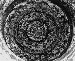
Synchronous off-center rotation occurs when the center of the bit orbits the center of the hole in the rotary direction once per revolution. This rotation results in rings of uncut rock on the hole bottom and deep grooving of the cone steel between adjacent rows in addition to sculpting within a row (Fig. 2).
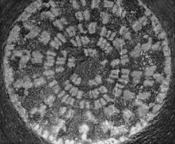
With conventionally designed roller cone bits, the teeth are arranged in circular rows on separate cones. The centers of successive rows form a spiral pattern on the bit. This design configuration assumes that each of the rows of teeth not contacting the hole wall will have sole responsibility for removing a particular ring of rock. Therefore, tracking occurs when teeth within a particular row align with craters formed during previous rotations of the same row (Fig. 3 [62445 bytes]). This tendency suggests that altering the pitching schemes within individual rows would combat tracking.
Previous studies have focused on random tooth arrangements or kinematic bit models.5 6 The fact that a particular layout is based on random cutter placement does not in itself eliminate the propensity of a bit to track. Existing methods neither quantify tracking for a selected design nor provide a means for eliminating tracking.
Analyzing individual cutter rows allowed development of a numerical technique to calculate tracking coefficients. The algorithm requires the tooth count and row diameter as inputs, applies pertinent engineering constraints (for example, minimum section between adjacent inserts), and produces a set of ranked antitracking insert layouts.
The tracking coefficient, called trackability, is also used to compare manually chosen pitching schemes and determine the best selection for a given design. Trackability numbers range between zero (least likely to track) and one (most likely to track) and are similar to probability coefficients.
Tracking causes excessive cone wear between teeth (Fig. 1).
Off-center rotation bottom hole pattern (Fig. 2).
Experimental results
Laboratory trackability tests were performed on a drilling machine. This apparatus is a vertical lathe engineered to accept a 6-ft diameter rock cylinder as the work piece. The test wheel rotates on a pin attached to an instrumented shaft (Fig. 4 [62445 bytes]).
Three single-wheel cutters were designed with different trackability coefficients. A cutter with evenly spaced teeth had a trackability of 1, a cutter with intermediately spaced teeth had a trackability of 0.55, and a cutter with aggressively spaced teeth had a trackability of 0.22.
The cutter is advanced vertically at the beginning of each pass and held rigidly at a fixed depth of cut (DOC) of 0.08 in. The test wheel is fed radially across the rock face to the center and returned back across the rock face without vertical advancement, equivalent to 0.00 in. DOC.
Several successive passes were taken with each test wheel to observe characteristic rock rib development. Loads were measured from the cutter holding fixture. Crater patterns formed on the rock were visually compared to measure the alignment between adjacent craters.
Tests performed on concrete and Gabbro yielded similar results. Each cutter wheel produced distinct crater patterns. The evenly spaced teeth on the symmetric wheel generated large regularly spaced rock ribs. The rock rib height matched the full projection of the cutter teeth, thereby bringing the cutter steel into contact with the rock. The cutter steel between the teeth was heavily pitted and plastically deformed by contact with the rock ribs.
The loads measured on the zero DOC passes attempted to estimate the related success of the previous cutter passes at removing rock. As the uncut rock ribs grew larger, however, the symmetrical wheel simply indexed and tracked. The rock ribs also aligned radially in spokes from the center to the outer diameter of the rock.
This alignment revealed the sensitivity of rolling cutter rows to craters created by neighboring rows. The intermediate cutter (0.55 trackability) produced smaller rock ribs with shorter spokes, but contact with the rock still heavily pitted the cutter steel.
Conversely, the aggressively spaced cutter made a random crater pattern with minimal rock ribs and no visible radial alignment. The cutter steel was pitted only lightly by rock rib contact.
The vertical load was a good indicator of tracking. Each cutter started with a flat rock and made several 0.08-in. DOC passes. As the accumulated depth of cut increased, the loads required by each cutter diverged because of the differing buildup of rock ridges (Figs. 5 [51945 bytes] and 6 [51634 bytes]). The symmetrical cutter required 41% more load on the last pass than the aggressive cutter and 25% more than the intermediate cutter (Fig. 5 [51945 bytes]).
Evenly spaced cutter layouts are often applied to hard formation TCI bits to maximize insert density. The intermediate spaced cutter represents the primary layout on soft formation bits, featuring a few "broken" pitches placed within an otherwise symmetrical row.
The aggressive wheel reveals the untapped commercial opportunities available when this technique is included in the process of designing and manufacturing roller cone bits with minimal tracking tendency. These laboratory tests show that using pitching schemes with low trackability coefficients can decrease both cone shell erosion and the axial thrust required to drill a set rate of penetration. Reduced weight on bit equates to improved drilling efficiency; decreasing the bearing and heat loads extends bit life.7
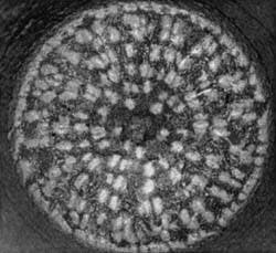
An antitracking IADC 437 bit provides better bottom hole coverage (top). The teeth from a standard IADC 437 tracked, leaving ridges of uncut rock (bottom). The tooth indentations are lighter, and the wet marble rock is darker in these photos (Fig. 7).
Simulator tests
A 121/4-in. Type 437 (International Association of Drilling Contractors bit code) bit was redesigned after analysis of dull bits returned from the field and laboratory tests showed tracking was responsible for bit wear and tooth breakage.
The new design included features for antitracking and improved gauge holding ability.8
Full-scale simulator drilling tests were conducted with both the standard and new designs. Rotary speeds were 70, 140, and 210 rpm in Mancos shale at 2,100-psi bottom hole pressure.9 The control system set the drillstring vertical feed rate (rate of penetration) to 15 ft/hr with a flow rate of 500 gpm of 9.4-ppg lignosulfonate mud.
In these downhole simulation tests, the new design outperformed the standard design by requiring 10-22% less weight on bit to drill at the same penetration rate. Improvements in specific energy, the amount of mechanical energy input required to remove a unit volume of formation, ranged 5-20%.7 For these fixed rate-of-penetration tests, the performance improvement varied proportionally with DOC and inversely with rotary speed.
Tracking aside, the drop in performance improvement with increasing rotary speed verified that controlling bit balling in shales depends on many factors, such as gauge design, hydraulics, environment, and operating parameters.10
The standard and new IADC 437 designs then test drilled Carthage marble under atmospheric conditions. Penetration rates of 5-60 ft/hr at rotary speeds of 60 and 120 rpm were evaluated.
The new IADC 437 design reduced tracking, improved performance, and provided better bottom hole coverage (Fig. 7). In these figures, the tooth indentations are lighter, and the wet marble rock is darker.
Teeth on the standard roller cone bit indexed such that indentations were spaced in angular groups with radial regularity. Angular grouping primarily depends on intrarow tracking, while radial regularity is a consequence of interaction with neighboring rows. Similar observations were previously noted on the single-wheel test machine.
Field tests
As a result of numerical and laboratory analysis, the new 121/4-in. IADC 437-type bit was run in the North Sea (Table 1 [13469 bytes]).
The new design resulted in a dramatic improvement in bit life at similar parameters. This design maintained the rate of penetration for 13% more hours at a greater depth and drilled an average of 16% more footage. Step improvements in bearing and seal effectiveness were also realized from improved drilling efficiency and enhanced gauge cutting features.
Dull bit analysis indicated tracking was a major concern with the 77/8-in. IADC 547-type bits used in southeast New Mexico. An experimental version of a 77/8-in. IADC 547 bit was redesigned to incorporate low trackability pitching schemes. Except for the new pitching scheme, this bit was identical to the standard design. Test bit penetration rates were equivalent to those from the best offsets, and cost per foot was consistently matched or reduced (Table 2 [27775 bytes]).
Systems thinking dictates that limited effort should be expended, separating effects for diverse environmental conditions from singular design changes, as dictated by linear analysis.11 Thus, future development should focus on the whole system by combining antitracking technology, gauge cutting structure enhancements, and materials technology improvements.
Results
Tracking increases the load required to drill at a given rate and decreases drilling efficiency and bit life. Where tracking is the limiting factor, it is possible to improve drill bit performance by improving tooth arrangements.
Carefully chosen intrarow tooth arrangements can effectively combat tracking. These arrangements vary the distance between successive teeth and reduce the probability that teeth will consistently fall in existing craters.
Single tooth row atmospheric tests, full-scale simulator testing, and field tests validated an algorithm for estimating tracking propensity. Application of this technique in the design of roller cone bits improved drilling performance and verified the predictive capabilities of this technique. A proprietary numerical technique can predict the relative tracking performance of tooth row pitch schemes. This technique provides a measure of the tracking properties of each pitching scheme to assist the designer in cutter layout.
Aggressive pitching schemes improved 121/4-in., IADC 437-type drilling in the North Sea and 77/8-in. IADC 547-type drilling in New Mexico.
Acknowledgment
The authors thank Hughes Christensen Co. for permission to publish this article. The authors also thank Jim Redden for preparing the manuscript, Tommy Harris for assisting with field data, and Matt Isbell for help with laboratory testing.
References
1. Schmidt, S.R., Wittry, A.E., Burr, B.H., and Kelly, J.L. Jr., "Metal Bearing Seal Technology Improves Drilling Efficiency of Rolling Cutter Bits in High-rpm North Sea Applications," paper No. 21934, presented at Society of Petroleum Engineers/International Association of Drilling Contractors Annual Drilling Conference, Mar. 11-14, 1991, Amsterdam.
2. Kenner, J.V., and Isbell, M.R., "Dynamic Analysis Reveals Stability of Roller Cone Rock Bits," paper No. 135148, presented at the SPE Annual Technical Conference & Exhibition, New Orleans, Sept. 26-28, 1994.
3. Kenner, J.V., and Isbell, M.R., "New Energy Decomposition Study For Rolling Cone Rock Bits," American Society of Mechanical Engineers Drilling Technology Transactions, PD-Vol. 65, pp. 163-78.
4. Isbell, M.R., Besson, A., and Torgerson, T.A., "Unique Roller Cone Bit Design Improves Economics of Soft Formation Drilling," paper No. 27469, presented at the SPE/IADC Annual Drilling Conference, Dallas, Feb. 15-18, 1994.
5. Ma, D.K., and Yang, S.L., "Kinematics of the Cone Bit," SPE Journal, June 1985, pp. 321-29.
6. Naganawa, S., Tanaka S., and Sugaya, N., "Experimental and Theoretical Analysis of Roller Cone Bit Vibrations," ASME Energy-sources Technology Conference and Exhibition, Houston, Jan. 29-Feb. 1, 1995.
7. Pessier, R.C., and Fear, M.J., "Quantifying Common Drilling Problems with Mechanical Specific Energy and a Bit-Specific Coefficient of Sliding Friction," paper No. 24584, presented at the Society of Petroleum Engineers Annual Technical Conference and Exhibition, Washington, D.C., Oct. 4-7, 1992.
8. Pessier, R.C., Grimes, R.E., Isbell, M.R., and Scott, D.E., "Rolling Cone Bits with Novel Gauge Cutting Structure Drill Faster, More Efficiently," paper No. 30473, presented at the SPE Annual Technical Conference and Exhibition, Dallas, Oct. 22-25, 1995.
9. Ledgerwood, L.W., and Kelly, J.L., "High Pressure Facility Re-Creates Downhole Conditions in Testing of Full Size Drill Bits," paper No. 91-PET-1, presented at the ASME Energy-sources Technology Conference and Exhibition, New Orleans, Jan. 20-24, 1991.
10. Pessier, R.C., Fear, M.J., and Wells, M.R., "Different Shales Dictate Fundamentally Different Strategies in Hydraulics, Bit Selection, and Operating Parameters," paper No. 28322, presented at the SPE Annual Technical Conference and Exhibition, New Orleans, Sept. 25-28, 1994.
11. Koerner, R.H., "Connections With Hard Technology," Journal of Petroleum Technology, May 1995, pp. 350-52.
Based on a presentation at Energy Week Conference & Exhibition in Houston, Jan. 29-Feb. 2.
The Authors
John V. Kenner is technical services manager for Hughes Christensen Co. in the Woodlands, Tex. He joined Hughes Christensen Co. research in 1991 after completing an MS in mechanical engineering at the University of Texas at Austin. His interests include drilling mechanics, isolated bit dynamics, and bit/drillstring system dynamics.Prior to joining Hughes Christensen, Kenner was a senior durability and damage tolerance engineer for LTV Aircraft Products Group in Dallas. He holds a BS in aeronautical engineering.
Turlach Boylan graduated from Queen's University, Belfast, with a masters of engineering in 1989. He worked for Hughes Christensen Co. for 6 years in rolling cutter drill bit design and in research. In 1995, Boylan formed Transatlantic Technical Services, a software consulting company in Houston.
Copyright 1996 Oil & Gas Journal. All Rights Reserved.
