Mathematical technique improves directional well-path planning
P. V. R. Suryanarayana, Roger C. McCann, Randall L. RudolfA procedure that uses nonlinear optimization theory to plan complex, three-dimensional well paths and path corrections provides an alternative and improved method to plan horizontal and directional well paths.
Mobil E&P Technical Center
DallasRajnish A. Rupani
PicoSoft Inc.
Dallas
The technique uses a sequential gradient restoration algorithm (SGRA) with scaling, modified prerestoration, and one dimensional step-size search with cubic interpolation to quickly and efficiently arrive at an optimal solution.
Over the past 4 years, this computer-based program has been used by several Mobil Corp. affiliates to plan well paths for horizontal and directional wells worldwide.
When planning a horizontal or directional well path, the objective is to describe a trajectory that reaches a given target from a given starting location, subject to various constraints. The starting location may be the surface location for planning or a point on an existing path for path-correction or sidetracking.
The target may be a single point, a two-dimensional region (rectangle), or a three-dimensional region (box), which must be reached at specified inclination or azimuth. In general, the well-path is a three-dimensional curve; in other words, it does not lie on a plane.
It is customary to represent the well-path as a combination of planar turn and straight sections. When defining the well path, the limitations that are placed on the curvature and length of turn sections, lengths, inclination and azimuth of straight sections, and the kick off point (KOP) will constrain the resulting profile.
In general, there are more unknown parameters for the complete well path than there are defining equations. Consequently, the problem of finding a well path is underdetermined. This usually means there is an infinite number of potential well paths that will satisfy the constraints while still hitting the desired target.
Several well-planning programs are commercially available to solve the problem of finding an appropriate horizontal or directional well path. However, all of these use a trial-and-error procedure.
Typically, these programs convert the under-determined problem into a fully determined problem by requiring the user to select a value for a sufficient number of the parameters, then using a trial-and-error procedure to arrive at a satisfactory well path.
This is sometimes augmented by heuristic rule bases. These procedures are time consuming and depend on the user's experience. In addition, these techniques are limited to simpler well paths which may not find the optimal path to the target, especially since the trial-and-error search is usually arbitrary and user-driven.1
Mathematical optimization theory provides a much more sophisticated, rigorous, and efficient approach to solve these problems. Although optimization has been used in other areas of the oil industry, it has not been considered for well planning until very recently. In the literature, very few references discuss its use for well planning.
Wu, et al., describe the use of an optimal-control approach with calculus of variations to determine a least-length well path, resulting in a combination of optimal sub-arcs that provide a minimum-length trajectory.2
Helmy, et al., (1997) use a Sequential Unconstrained Minimization Technique to determine a minimum-length well path, subject to build and drop-rate restrictions, for a two-dimensional, S-shaped well.1
General well path
Consider a general three-dimensional well path that reaches a given target. The well path can be described in a Cartesian-coordinate system having its origin at the surface starting location, with x-axis representing North/South (positive x being North), y-axis representing East/West (positive y being East), and the z-axis (z positive downwards) representing true vertical depth (TVD). With arc length s as a parameter, a point P(s) anywhere on the curve is then completely described by its coordinates x(s), y(s), z(s), the inclination q (s), and azimuth f(s) (Fig. 1 [12,360 bytes]). This is standard oil field terminology and is retained for convenience.In order to simplify the problem, we idealize the well path to contain a finite combination of curved and straight sections. In current practice, well-paths are often described this way, with the arc-length s referred to as the measured depth (MD).
For such an idealized well path, the end point of the path can be completely defined by scalar equations in terms of several independent parameters of the profile, such as turn rates or turn lengths of each turn section, inclination, azimuth, and length of each straight section.
If there are n independent parameters of the problem, represented by the vector x, q scalar equations that determine the end point of the path (q < n), the problem becomes one of finding x such that the end point of the path coincides with the target.
In general, there are only three equations-one for each coordinate-that describe the end point, unless some parameter values are fixed. Since there are greater than three parameters (n 3) for even the simplest of two-dimensional well paths, the problem is generally underdetermined.
For purposes of illustration, consider a well path with two turns and two straight sections (Figs. 2a and 2b [20,439 bytes]). Such a profile is most commonly considered by existing well-planning programs.
For a well path starting from a surface location, the path profile remains vertical until it reaches the KOP, (x = y = 0, z = zo, q = f = 0). It then deviates from vertical with a turn rate a1, until it reaches an inclination of qh (hold inclination), at an azimuth of fh (hold azimuth). The profile remains at this inclination and azimuth for a length Lh (hold length). It then turns at a rate a2 until it reaches the inclination qt and azimuth ft (target inclination and azimuth), remaining straight for a length of Ls (ending straight section) before reaching the target at coordinates xt, yt, and zt.The profile may continue through the target for a specified length shown as the target length in Fig. 2a. When the target azimuth is different from the hold azimuth, the well-path becomes three-dimensional as shown in the top view of Fig. 2b.
For a profile starting from a point on an existing path such as a sidetrack or path corrections, the starting point has non-zero coordinates xo, yo, zo, qo, and fo.This double-turn profile will be used to illustrate the procedure, keeping in mind that the procedure can be used for any general path with more holds and turns.
Problem formulation
The problem is formulated by assuming that a well path consists of the components described above. If the well is being planned, the starting point is the KOP. If the well is being drilled, the last survey depth becomes the plan starting point. For the double-turn profile, there are seven independent unknown parameters (n = 7) as shown in Fig. 2. These parameters constitute the vector x, as shown in Equation 1 [71,986 bytes] (Equation box). It is assumed that the target has to be reached at a prescribed inclination and azimuth. If this was not the case, the target inclination qt and azimuth ft will also become unknown parameters, resulting in a 9-vector for x.Using the minimum radius of curvature method,3 the end-point of the well path can be completely described in terms of x, defined by Equations 2a, 2b, and 2c. The requirement that the end point of the well path coincide with the target provides three scalar equality constraints of the form shown in Equations 3a, 3b, and 3c.
The problem now becomes one of finding x such that the equality constraints of Equation 3 are satisfied. Since there are seven unknowns, and only three equality constraints, the problem is underdetermined, as stated earlier. The traditional trial-and-error methods solve the problem by requiring the user to select values for four of the parameters, and solving for the other three in a fully determined system with three equations and three unknowns.
The solution then proceeds in an iterative fashion, with the user selecting different combinations of parameters, until a satisfactory solution is reached. As mentioned earlier, this approach is cumbersome and time-consuming. Also, it is applicable only for simple profiles, often yielding suboptimal solutions if it can find a solution at all.
In addition to satisfying the equality constraints (Equations 3), the solution also has to satisfy several inequality constraints. In the simplest case, these constraints impose a range on each of the parameters of the problem, which in general, are of the form shown in Equation 4.
In the case of the double-turn profile under consideration, the range constraints on the seven parameters are shown in Equations 5a-5g. These range constraints allow the user to set realistic limits on the values of the parameters, depending upon operational, geologic, or physical limitations.
In trial-and-error techniques, the user attempts to satisfy these constraints heuristically, sometimes settling for an "acceptable" violation of some of them.
In general, inequality constraints need not be as simple as shown above, and could be any well-defined function involving the parameters of the problem. For instance, inequality constraints may be used to set limits on the starting and ending TVD of a straight section, since the starting and ending TVDs can be expressed as functions of x.
The approach described in this work can handle inequality constraints of any kind, as long as they are well-defined functions of x.
The above 7 range constraints provide 14 distinct inequality constraints. These inequality constraints can be converted into equality constraints by introducing slack variables.4 Because each inequality constraint introduces a new slack variable, there is no limit to the number of admissible inequality constraints.
Optimization
In order to set the problem up as an optimization problem, it becomes necessary to choose the objective function that needs to be optimized, otherwise known as the optimality criterion. Several criteria or combinations of criteria may be used as long as they are well-defined functions of the problem parameters.In this work, the criterion is to obtain a solution well path with parameters as close to a preferred set of parameters as possible. Equation 6 states this criterion mathematically.
The subscript p in Equation 6 refers to the preferred values of the parameters.
a'1=100/a1 and a'2=100/a1are convenient definitions that simplify the constraint equations. The 1/2 is inserted for convenience in finding derivatives, and does not affect the solution. Also note that each term is scaled with respect to the preferred value.
The problem is now one of minimizing the optimality criterion of Equation 6, subject to the equality constraints of Equations 3 and the inequality constraints of Equations 5. Stated simply, the user must find the unknown parameters that describe a well path that hits the target within specified tolerances, such that the parameter values are within the prescribed range constraints, and as close to the user-preferred values as possible.
As noted earlier, all equations that describe the problem, including the objective function, are scaled. It is very important that the problem parameters, objective function, and equality and inequality constraints be scaled appropriately for the well-planning problem, especially since the natural orders of magnitude of the parameters and constraints are vastly different.
For example, turn rates can be about 2°-10°/100 ft, while lengths of straight sections are of the order of hundreds of feet. Scaling also allows the use of weighting scalars as described below. Poorly scaled implementation of any optimization procedure leads to convergence problems and suboptimal solutions.5
The gs in Equation 6 are weighting scalars. Weighting scalars can be used to set the relative importance of each parameter in the optimality criterion. For instance, if the scalar takes integer values between 0 and 5, it can be used to set the "rank" of each parameter.A rank of zero sets the value of the scalar to zero, thus eliminating the contribution of that parameter to the optimality criterion. A relatively high rank for a parameter, such as 5, increases its contribution to the optimality criterion, forcing its value closer to the preferred result than parameters with lower rank. In well design, ranking is useful in fine-tuning the solution.
Optimization procedure
The optimization conditions that must be satisfied are shown in Equations 7-10. Equation 7 results from the standard first-order condition that the first derivative of the objective function f, or equivalently, the augmented function F of Equation 10, vanish at a minimum. In practice, it is necessary to seek satisfaction of this condition within a preselected small tolerance, e4. Q is the error in the optimization condition. Equations 8 represent each of the three equality constraints that must be satisfied for the end point of the well path to coincide with the target. In practice, the target is not a fixed point, and there is always a tolerance within which the target may be reached. e1, e2, and e3 are the user-specified target tolerances on the North/South coordinate, East/West coordinate, and the TVD, respectively. Equation 9 is the requirement that all the inequality constraints be satisfied. P is the error in their satisfaction. In practice, the user seeks the satisfaction of these inequality constraints within a preselected small tolerance, e5.Thus, the problem becomes that of finding an x that satisfies all of the above conditions. Note that the same conditions in Equations 7-9 are applicable regardless of the optimality criterion and additional constraints. In this way, the problem of planning a well path or path correction is posed as a problem in nonlinear optimization.
Implementation
Optimization can be performed using any of several techniques. However, in this work, Mobil prefers the sequential gradient-restoration algorithm (SGRA), 6 with scaling, 5 prerestoration, 4 and a modified one-dimensional search used for the optimal step-size. 7The SGRA, which was originally developed to solve the problem of optimal aircraft trajectories for safe landing in wind shear, is a robust, efficient algorithm with superior convergence properties when compared to many other techniques.8 9
Moreover, it needs only first-derivative information, unlike methods based on quasilinearization, and is not subject to convergence problems like the penalty function methods.10 It can also be easily extended to optimal control problems.11
SGRA is composed of an alternate succession of gradient phases and restoration phases. The basic approach is shown in Fig. 3 [21,668 bytes]. The process begins with an initial guess for the parameter values, the nominal point Xnom.
In general, Xnom does not satisfy the constraints of the problem. In the restoration phase, which proceeds along a minimum-distance path, the values of parameters are varied and "restored," such that all the constraints of the problem are satisfied within preselected tolerances so that Equations 8 and 9 are satisfied.
At the end of this phase, the user arrives at a restored point, such as Xrest,1 in Fig. 3, within the constraint boundary. In the gradient phase, a single step is taken along the gradient, arriving at a point Xgrad,1, such that the value Q of the objective function is reduced (the error in the optimality criterion is reduced), and the solution moves towards the optimum.
This movement is based only on the first derivative information at the nominal point, and an optimal step size is chosen such that the step size is large enough, the descent property is maintained, and constraint violation is minimal. This procedure continues, with alternating restoration and gradient phases, until the optimum is reached.
Because the constraints are satisfied at the end of each restoration phase, the parameter values at the end of any restoration phase provide a well-path that reaches the target within prescribed tolerances and constraints.
The above procedure has been implemented using a desktop computer program. The user inputs the target coordinates and allowable tolerances within which the target may be reached. Then, the constraints on the parameters are chosen, reflecting physical, operational, or geologic constraints on turn rates, hold sections, and so on.
Finally, the preferred values for each of the parameters are chosen, based on available directional drilling tools or other operational requirements. The user also chooses the rank or relative importance of each parameter. For example, is the need for turn rates to be close to preference greater than that for the hold inclination.
Given these inputs, the program computes values for the parameters such that:
- They are within specified constraints.
- They are as close to preferred values as possible, subject to user-ranking.
- The resulting profile reaches the target within the desired tolerance.
Example
The following is a well planning and drilling example for a well in the Gulf of Mexico using the following parameters:
- KOP (fixed) = 556 ft
- Target = 1,492 ft TVD
- North/south = -42 ft
- East/west = 866 ft
- Inclination = 89.7°
- Target azimuth = 90°
- Depth tolerance = ? 10ft
- Coordinate tolerance = ?10 ft.
Table 2 [5,927 bytes] shows the results of the calculated well plan. Since the hold length was fixed at 50 ft, it is exact, while the other parameters are close to the preferred values. If changes in the well plan become necessary, the user can change the preferred values, ranges, or the parameter rank to calculate a more-desirable well plan.
Fig. 4 [6,806 bytes] and Fig. 5 [6,605 bytes] show the vertical section and top view of the well plan. Note that the target is 42 ft south of the surface location, requiring a three-dimensional well path to hit the target at the desired inclination and azimuth. This can be seen in the top view.
The well started drilling as planned. As shown in Fig. 6 [10,275 bytes], however, it is clear the first build section did not build as fast as planned. This required a change in the plan to to hit the target.
The program computed a correction run. The same input values as shown in Table 1 above were used. Table 3 [4,784 bytes] shows the revised well plan. Note that the maximum build rate allowed was used to calculate the corrected well-path.
Discussion
The above examples show the power of optimization techniques when it comes to planning well paths and path corrections. The procedure is very efficient, robust, and quick as long as a solution exists within the specified constraints.This allows the user to fine-tune the solution and try several scenarios very quickly. Moreover, the entire problem is cast in an intuitive way, so that the user can focus on real-world issues and reflect these in the inputs, while the issues associated with optimization are handled mathematically.
This procedure clearly represents a significant improvement over the traditional trial-and-error techniques. The procedure can be used at all stages of drilling directional wells, from the planning stages, when feasible paths are planned in conjunction with geologists, to the rig site, where quick path corrections are needed.
Although the methods show the procedure for the double-turn profile, it can easily be applied to a general well path with a finite combination of turns and straight sections. This procedure can also be easily extended to include targets with no specified inclination or azimuth, multiple targets, and additional constraints.
There is no limit on the number of inequality constraints that are admissible; however, the number of equality constraints is limited at most to the total number of independent parameters in the problem. The procedure can also be modified to include other optimality criteria, including well paths that minimize torque and drag, or even cost.
It is versatile enough to be applicable to a wide range of problems where optimal solutions to oil field problems are desired. This procedure can be extended to planning wells that use systems of dynamic steering. In fact, optimization techniques are eminently appropriate for taking advantage of dynamic steering, where the turn rates can be dynamically controlled.
The problem then becomes one of optimal control, where the objective is to minimize a function, such as length or torque and drag, subject to both differential and nondifferential constraints. It is conceivable that a down-hole processor with appropriate algorithms can someday implement these procedures in real time.
References
- Helmy, M.W., Khalaf, F., and Darwish, T., "Well Design Using Computer Model," SPE paper 37709, presented at SPE Middle East Oil Show and Conference, Manama, Bahrain, Mar. 15-18, 1997.
- Wu, H-C, Kuehn, J.L., Ziaja, M.B., and Patten, W.N., "Optimal Wellbore Planning for Deviated Wells," presented at the ASME Energy Sources Technology Conference and Exhibition, Houston, Jan. 23-26, 1994.
- American Petroleum Institute, "API D20: Bulletin on Directional Survey Calculation Methods and Terminology," Washington, D.C., 1985.
- Miele, A., Calabro, A., and Rossi, F., "The Prerestorative Step in the Sequential Gradient-Restoration Algorithm for Mathematical Programming Problems with Inequality Constraints," Applied Mathematics and Computation, Vol. 3, 1977, pp. 265-80.
- Gill, P.E., Murray, W., and Wright, M.H., "Practical Optimization," Academic Press, New York, 1981.
- Miele, A., Huang, H.Y., and Hiedeman, J.C., "Sequential Gradient-Restoration Algorithm for Minimization of Constrained Functions-Ordinary and Conjugate Gradient Versions," Journal of Optimization Theory and Applications, Vol. 4, No. 4, 1969, pp. 213-43.
- Miele, A., Bonardo, F., and Gonzalez, S., "Modifications and Alternatives to the Cubic Interpolation Process for One-Dimensional Search," The Arabian Journal for Science and Engineering, Vol. 4, 1979, pp. 121-28.
- Levy, A.V., and Guerra, V., "On The Optimization of Constrained Functions: Comparison of Sequential Gradient-Restoration Algorithm and Gradient-Projection Algorithm," Applied Mathematics and Computation, Vol. 2, 1976, pp. 283-309.
- Huang, H.Y., and Aggarwal, A.K., "A Class of Quadratically Convergent Algorithms for Constrained Function Minimization," Journal of Optimization Theory and Applications, Vol. 16, Nos. 5/6, 1975, pp. 447-85.
- Miele, A., Cragg, E.E., Iyer, R.R., and Levy, A.V., "Use of the Augmented Penalty Function in Mathematical Programming Problems, Parts 1 and 2," Journal of Optimization Theory and Applications, Vol. 8, No. 2, 1971, pp.115-53.
- Gonzalez, S., and Miele, A., "Sequential Gradient-Restoration Algorithm for Optimal Control Problems with General Boundary Conditions," Journal of Optimization Theory and Applications, Vol. 26, No. 3, 1978, pp. 395-425.
Bibliography
Rudolf, R. L., Suryanarayana, P. V. R., McCann, R. C., and Rupani, R. A., "An Algorithm and Program to Plan Optimal Horizontal Well Paths," presented at the ASME Energy Sources Technology Conference and Exhibition, Houston, February 1998.Suryanarayana, P. V. R., and McCann, R. C., "Horizontal Well-Path Planning and Correction Using Optimization Techniques," Presented at the ASME Energy Sources Technology Conference and Exhibition, Houston, February 1998.
The Authors
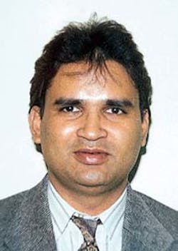
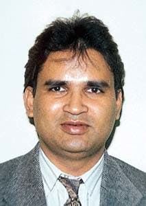
P. V. R. (Suri) Suryanarayana is a senior engineer at Mobil E&P Technical Center in Dallas. His current areas of interest include drillstring and tubular mechanics, thermal and fluid sciences, reliability-based design, coiled tubing, and underbalanced drilling. Suri has a Bachelor's degree from the Karnataka Regional Engineering College in India, an MS from Mississippi State University, and a PhD from Rice University, all in mechanical engineering.
Roger C. McCann is a senior research advisor at Mobil E&P Technical Center in Dallas. He has a BA from Pomona College, and MS and PhD degrees from Case Western Reserve University, all in mathematics. His primary area of interest is mathematical modeling of drilling-related phenomena such as hydraulics, drillstring mechanics, wellbore stability, and differential sticking.
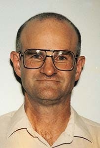
Randall L. Rudolf is a senior drilling advisor at Mobil E&P Technical Center. He has a BS in mechanical engineering from Oklahoma State University. He is currently responsible for the development and maintenance of engineering simulation software for Mobil's drilling and production engineers, and provides technical advice to operating affiliates in a wide range of drilling problems.
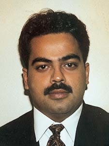
Rajnish A. Rupani is the president of PicoSoft Inc., a Dallas-based software company. He received his BS in electrical engineering from Texas A&M University in 1987. Rupani has been working as a software engineer for the last 10 years with a primary focus on engineering application development.
Copyright 1998 Oil & Gas Journal. All Rights Reserved.
