Apparatus eliminates earthen pits in air-drilling operations
Jerry A. Rusnak
New Prospect Drilling Co.
Greenwood, Ark.
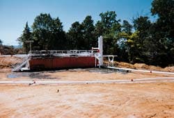
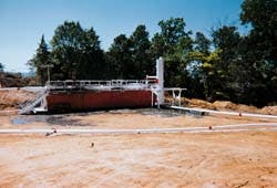
On location in the Arkoma basin, the main separation unit (MSU) replaced the conventional earthen pit and allowed drillers to operate in areas that would otherwise be restricted because of environmental concerns. The well-bore exhaust passes through a 16-in. OD, white horizontal pipe that runs along the top of the orange steel pit. Water is injected along the top portion of the pipe through a series of 2-in. valves. Along the bottom, another series of 4-in. valves allow cuttings and most of the liquids to be flushed into the steel pit. The white vertical tank mounted on the right side of the steel pit separates gases and the remaining liquids (Fig. 1).Earthen pits used in air-drilling operations can be eliminated by using an apparatus equipped to separate, treat, and transfer liquid and solid portions of the drilling effluent while exhausting only the gaseous components such as air and methane to the atmosphere.
This low-pressure system has provided a solution to many of the problems such as spillage and leakage associated with the conventional use of earthen waste pits. With proper planning and use, it should provide a safe, simple, and economical alternative to current practices. Given the costs associated with earthen pit systems and their environmental risks, a closed system such as the one described in this article should gain wider acceptance.
Range of operations
Field-testing showed the apparatus can handle continuous liquid volumes of 90 bbl/hr with the capability to handle even higher volumes during peak loads. It can also handle continuous solid volumes of 14 bbl/hr (80 cfh).During continuous drilling operations, the apparatus (Fig. 1) handled maximum gas-production rates of 1,250 Mcfd with air-injection volumes ranging from 1,600 to 3,200 scfm. Water-injection volumes ranged from 10 to 20 bbl/hr and drill bit sizes used during the test program ranged from a maximum of 15 in. to a minimum of 77/8 in.
These parameters adequately encompass a large portion of the operating conditions for most air-drilled wells in the Arkoma basin of northwest Arkansas and southeast Oklahoma where the system was tested. This basin produces dry natural gas (methane). Many of the wells in this basin are drilled underbalanced using compressed air.
Earthen pits
There are five problems associated with using an earthen waste pit to catch the effluent created while drilling with air or air/mist:- All fluids that collect in the waste pit, including rainwater and runoff, must be disposed of by trucking, well injection, or treatment for land disposal. In all cases, the cost for disposal ranges from $1 to $3/bbl. Depending on the local topography, the volume of liquids collected from runoff can be several times more than the volume produced or injected while drilling several times over. Estimated total costs to dispose of waste pit fluids range from $1,000 to $30,000/well.
- If the fluids in the waste pit become contaminated with a hazardous material such as used oil, diesel fuel, or oil-based mud (OBM), the whole pit volume may be classified as hazardous. Disposal costs per barrel can increase tenfold.
- Construction and reclamation of the earthen pit can be very expensive in areas where the earth is very hard or very soft. Fracturing or lack of compaction can also require the use of expensive liners to prevent the pit from leaking. Cost of pit construction and reclamation ranges from $1,000 to $10,000. Costs of pit liners range from $3,000 to $7,000.
- Flash flooding or pit-wall failure can cause large-volume spills onto adjoining land or into nearby water bodies. Costs including fines to remediate a pit spill can run more than $10,000.
- At some locations, particularly inside city limits and state parks, earthen waste pits are prohibited.
Main separation unit
The main separation unit (MSU) consists of a 16-in. OD x 40-ft long horizontal pipe with a series of 2-in. inlet valves located on top and 4-in. outlet valves located on bottom. In addition, a series of steel baffle plates are installed on the inside of the pipe.A 30-in. OD x 16 ft high vertical pipe is located near the closed end of the horizontal pipe with one 7-in. inlet and two 7-in. outlets. The MSU is mounted to the top of a steel pit that is 8-ft high x 10-ft wide x 45-ft long with three equal-sized compartments (Fig. 2 [73,510 bytes]).
The other major component is a 5-in. x 6-in. centrifugal pump powered by a 75-hp diesel engine. Finally, the MSU incorporates an ancillary safety device or panic line (Fig. 3 [59,913 bytes]) consisting of a hydraulic control valve (HCV) fitted to the flow line and plumbed to the closing unit.
When activated, the control valve closes the annular blow out preventor while simultaneously opening the flow-line valve, causing the well flow to bypass the MSU through a choke manifold and a separate 4-in. flow line routed to the burn pit.
Equipment operation
The outlet of the rotating control head is connected to the inlet side of the MSU by a 7-in. ID blooie line. The well-bore exhaust enters the MSU at Point A while, water is simultaneously injected through the series of 2-in. valves along Point B (Fig. 2). A series of 4-in. valves at Point C are adjusted to flush the drill cuttings and most of the liquid into the steel pit, while keeping the outlets flooded with liquid.The gases and the overflow of liquids are sent to a vertical separator at Point D. The remaining liquids are returned to the steel pit at Point E. The gases are sent to a burn pit from Point F. The liquids are circulated with a pump (G). The excess liquids are transferred to a holding tank for haul-off or some other reuse.
As an option, the pit can be equipped with a jetting system (H) and a shale shaker to continuously dewater (I) and remove cuttings (J) from the steel pit. Otherwise, the cuttings can be periodically removed with a small track hoe or similar implement.
Equipment operation
This apparatus was used on a total of eight wells and tested the equipment's capacity to handle the drilling process over a wide range of conditions. The main parameters that were evaluated included ( Table 1 [105,745 bytes]):- Produced solids volume
- Produced water volume
- Produced gas volume
- Injected water volume
- Injected air volume
- Total depth drilled.
Remote-controlled actuators were also added to the dump valves so that they can be operated from the rig floor. An injection pump was incorporated to inject a defoamer into the 7-in. blooie to prevent formation of a foam cap inside the steel pit.
The addition of a solids processing system enabled the pit to be cleaned out continuously, if drilling conditions did not allow for periodic cleaning. A dresser sleeve-type coupling attached to the blooie line and separator inlet allowed for a quick nippling-up once the surface or intermediate casing was run.
Modifications
Several significant events occurred during field testing. Some of these incidents resulted in alterations or additions while other circumstances revealed positive applications of the new system.Well No. 2 encountered very high-gas flow rates of 6,000 Mcfd that caused gas influx problems (Table 1). At that time, the end of the exhaust line was placed in close proximity to the main separation unit with a fixed pilot light mounted on the end. When a sudden gas influx unloaded all the fluid from the MSU, the 4-in. valves were manually operated, and before they could be closed, the escaping gas caught fire inside the steel pit.
The drilling crew shut the air off and began pumping drilling mud. The fire self-extinguished before the drilling mud returned to the surface. After completion of this well, the vertical separator was modified, and a flow line was extended to move the gas-exhaust end about 100 ft away from the MSU. In addition, pneumatic actuators (normally closed) were added to the 4-in. valves so that they could be controlled from the rig floor.
Well No. 5 encountered weather problems associated with ambient temperatures of less than 0? F. and wind chill factors in the 240° F. range. These problems could not be overcome. Line freezing along the circulation system occurred while attempting to air/mist drill.
In particular, the air lines from the mist tank to the kelly, including the kelly hose, had to be continuously thawed. Similar problems occurred with the circulating lines on the MSU. The operator elected to shut down the drilling operation for about 24 hr until the frigid conditions abated.
Nevertheless, this well was unique in that the well plan called for a switch from air to OBM once surface casing was set. This is a common practice in some areas of the Arkoma basin where major thrust faulting creates a condition of sloughing shales, making air drilling impossible.
Because regulations mandate that a closed mud system be used while drilling with OBM, the need to build an earthen waste pit just for the shallow air-drilled section becomes expensive, especially since it would be used only for the upper hole section. By using the MSU instead of an earthen pit, it was possible to have closed systems for the entire drilling operation, saving time and money.
In another case, park officials allowed Well No. 7 to use the MSU instead of prohibited earthen pits near the park's main water supply. The apparatus reduced the risk of seepage or spillage.
In a similar case and for the same reasons, Well No. 8 was drilled inside a city limits, where a local ordinance also prevented the construction of an open waste pit.
Acknowledgment
The author wishes to thank Billy Ray Suggs and Joe Mellott of Seagull Energy Co., Mike Oxley of Oxley Petroleum Co., and Larry Miller and Ron Chambers of New Prospect Drilling for their assistance in constructing and testing this apparatus as well as in the preparation of this article.References
- Ikohu, Chi U., Natural Gas Engineering, PennWell Books, Tulsa, 1980.
- Rusnak, Jerry A., "Separation System and Method for Separating the Components of a Drill Bore Exhaust Mixture," patent application No. 08/630, 365, Apr. 10, 1996.
The Author
Jerry A. Rusnak is the general manager of New Prospect Co. He has been with the company since 1985. Rusnak managed six rigs that have drilled more than 500 wells in the Arkoma basin. He holds a BS in Ocean Engineering from Florida Atlantic University (1977).
Copyright 1998 Oil & Gas Journal. All Rights Reserved.


