Norway's Aasgard Project Heads For Production Start
L.R. Aalund
Managing Editor-Technology
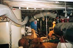
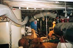
Activity is intense below deck as a huge workforce deals with a million man-hours of "carryover" work to get the Aasgard A FPSO ready for for sea trials late this year.
The massive project in the Norwegian Sea will eventually produce 200,000 b/d of crude oil and send 1.4 bcfd of natural gas deep into the heart of Europe. But it appears now production won't start until the first quarter of next year, perhaps in February. Original plans called for production to begin this month.
Estimates of the investment required have also increased, from 26.7 billion Norwegian kroner in 1995 to 33.1 billion kroner (about $4.4 billion) this past April, according to the Norwegian Ministry of Petroleum & Energy. Such big numbers seem reasonable when the scope of the project and the manpower, engineering, and technological resources and innovations required to do this are considered.
It's a daunting and dazzling project. Aasgard is the collective name for three fields, Smørbukk could be described as "the field from hell." The reservoir is deep, has high temperature, high pressure, lousy permeability, and other user-unfriendly characteristics.
But the project delay as of now is not because of drilling in the open sea or the installation of templates and lines in the complex subsea arena under 300 m of water (Table 1 [119,530 bytes]; Fig. 1 [380,021 bytes] ). That part is on schedule. The delay is because of the huge floating production, storage, and offloading (FPSO) vessel, Aasgard A (see cover).
The ship
As Fig. 1 shows, two ships, Aasgard A and C, and a gas production semisubmerisible, Aasgard B, are key elements in the production scheme. The Aasgard A will be the largest production ship in the world built to date.Per H. Kotte, a spokesman for Den norske stats oljeselskap AS (Statoil), the joint operator for Aasgard with Saga Petroleum AS, says that the crude oil going into Aasgard A will contain a tremendous volume of gas, which will be removed. Aasgard A thus will also be the largest floating gas treatment unit on the Norwegian shelf.
The ship will weathervane around a 26 m diameter moored turret that has 24 slots. Well streams from the subsea wells will be transferred via a swivel at the top of the turret to separators where gas and water will be stripped out. The ship is designed to treat and finish 200,000 b/d of crude and store some 900,000 bbl. The oil will be transferred to shuttle tankers for shipment to customers.
Getting this ship on location as near the originally planned time as possible has the highest priority. An earlier schedule had first oil production from Smørbukk starting this month (OGJ, Aug. 19, 1996, p. 50). That was only 31 months from contract award to commissioning.
But when the the hull arrived from Japan at the Aker AS Stord fabrication yards near Bergen last January, it was not as complete as originally planned. According to one source, 40 containers of equipment and instrumentaion remained to be installed,
The lack of completion of the hull when it arrived at Stord did not surprise Aker. It learned of the delays early in 1997 and began sending personnel from Aker Stord and Aker Electro to Japan for assessment of the situation. Back in Norway, drawings were being prepared and work packages prepared. The company said this past June that it had launched an accelerated work program that will put 4,000 workers on board the ship at peak construction time. In addition to its own topside work, Aker was faced with an additional 1 million man-hr of what a spokesman calls "carryover work" on the hull before the ship would be ready for sea trials.
Aker is now halfway through Phase II, the assembly, mechanical completion, and commissioning phase. The spokesman outlined two completion scenarios: One, which is a real challenge, according to the spokesman, will require intense attention and focus and put the ship out for sea trials at the end of October and oil on deck late in December. The second scenario has the ship sailing from Stord on Nov. 22 and oil on deck in January or February.
The current estimated overrun has pushed the breakeven oil price for Aasgard A up to $12/bbl, according to the respected Norwegian newspaper Dagens Næringsliv. This is a price that if anticipated earlier would have probably caused postponement of the project, a Statoil spokesman is quoted as saying.
An alliance
The key players in the ship project-Statoil, Saga, and main contractors Aker, ABB Oil, Gas & Petrochemicals, and Maritime Tentech-formed an alliance in 1996 in hopes that it would help meet the tight construction schedule. The contractors also believed the alliance would help win the contract against stiff international competition because the vessel was originally to be delivered under three separate contracts, according to the April 1996 issue of Aker Oil & Gas.The trio won the contract with Aker Engineering and ABB doing the topsides engineering and procurement, Aker Stord the vessel assembly and hookup, and Aker Electro the electrical work. Norway's Maritime Tentech engineered the vessel, which was built by Hitachi Zosen in Japan.
The operators and contractors have a large stake in avoiding an overun on the ship job, which, according to Aker, had a target cost of 2.3 billion kroner in 1996. Anything under this the four parties would split on an agreed upon basis. The two operators would get 50%, Aker 25%, and the other two 12.5% each.
On the other hand, all will have to kick in money at these percentages if there is an overrun of this target.
Floaters work together
Part of the gas stripped from the crude oil on Aasgard A will be injected into the reservoirs and the rest sent to the floating production gas platform, Aasgard B. This platform, which is 10 km east of the Aasgard FPSO and 7 km west of the Aasgard C storage vessel, will be put in operation in October 2000. It will will have the capacity to send at peak 40,000 b/d of crude to Aasgard A and 100,000 b/d of condensate to Aasgard C. It will supply 1.4 bcfd of rich gas to the gas processing plant at Karst via a new 450 mile long, 42-in. diameter line. At Karst the the lean gas will enter the 400 mile, 42-in. Europipe II line to Dornum, near Emden, Germany, and there connect to the European gas grid.Fig. 2 [86,433 bytes] shows the hydrocarbon flows in the entire Aasgard system. All this requires a large number of flexible risers that will face severe conditions. Table 2 [61,099 bytes] lists all the risers for Aasgard A, B, and C. Coflexip Stena Offshore Norway has been awarded the contracts for all of them. The one for the Aasgard B and C risers is worth nearly $95 million.
The produced water and gas injection risers will face pressures of 500 bar (7,250 psi), while the production risers are subject to 390 bar and 130° C. (275° F.). Engineering for the Aasgard B risers has started in Norway, and the pipe is set for delivery in March 2000.
Because of the severe conditions the flexible risers will face, a corrosion monitoring program has been set up by Robit Technology AS, a subsidiary of CorrOcean ASA. Each riser has fittings that permit the insertion of probes of the same polymer material that is used in the polymer-metal dynamic risers. The probe will be retrieved each 6 months, and a piece will be taken from it for laboratory testing. Any weight loss will represent line corrosion. Tests for thermal fatigue will also be performed, as well as direct measurement of fluid corrosivity through the fitting.
In addition, CorrOcean will monitor riser conditions by measuring vented gas between the individual layers in the flexible riser.
Engineer's nightmare
The three fields-Smørbukk, Smørbukk South, and Midgard-display major and in some cases radical differences. Smørbukk has the bulk of the oil reserves, while Midgard leads with gas reserves. Table 3 [44,926 bytes] gives reservoir parameters; Fig. 3 [75,468 bytes] shows typical well paths for each field.All in all, Aasgard, except for Midgard, is a petroleum engineer's nightmare. There are wells with "S" and "J" bore paths and horizontal wells requiring surgical precision to drill 1,000 ft horizontal sections and having high concentrations of hydrogen sulfide and corrosive formation fluids. The first three wells were drilled in Smørbukk in 1996. Almost 25 wells are scheduled to be drilled before oil ouput begins. All the wells, a total of 59, will be drilled and completed by 2003. As of last month, 17 had been drilled and one completed.
Transocean Offshore Inc.'s Transocean Arctic and Treansocean Winner rigs are currently drilling. The Tranocean Searcher and Saipem SpA's Scarabeo 6 are engaged in completion operations.
Smørbukk, compared with a normal Nowegian field, like Norne, has twice the reservoir depth, twice the pressure, twice the temperature, six times the carbon dioxide and seven times the hydrogen sulfide concentrations, eight times the gas/oil ratio, and 1000 to 500 times the flow resistance.
Kotte says Statoil has never had a challenge like this before. Regarding the frac jobs, he said, "At Smørbukk we are planning between 50 and 100 fracturing jobs with the small ones requiring 300 cu m of fluid and proppant, the large ones 500 cu m (3,145 bbl) of fluids and approximately 200 tons (400,000 lb) of proppant. This has to be pumped down in a formation with a pressure of 450 bar (6,526 psi).
"I don't think the oil world has seen anything like this before."
Statoil has awarded the Expro Group, Aberdeen, a contract to build a test tree for fracturing the Smørbukk reservoir. The tree, which will have an inside diameter of 6 in., is to be built to withstand 10,000 psi pressure and handle frac fluid with up to 12 ppg proppant at a rate of 40 bbl/min. Expro declines to discuss the problems it sees or potential solutions.
Earlier this year the company announced that it had successfully used a 5-in. ID, 10,000 psi subsea safety system for well-testing in a record-breaking depth of 4,200 ft or 1,280 m in the Gulf of Mexico.
Aasgard subsea
Idar O. Grytdal, manager of Aasgard subsea well systems, presented a progress report this past June on the subsea work at Aasgard, described the advanced equipment and hardware, and covered some problems.The subsea field work then was on schedule. He said that most of the facilities around Aasgard would be installed by the end of July (Fig. 1). Table 4 [34,773 bytes] lists the major subsea well systems that will ultimately go into Aasgard.
Grytdal said that, with all this complexity and four drilling rigs, standby vessels, survey vessels, and pipe-laying barges, there is a lot of traffic. In order to cut down on some of it, an underwater parking lot or subsea temporary infield (STIF) storage area has been established to allow short-time storage of subsea equipment or transfer of heavy equipment between vessels. The 30 m by 30 m area, which has been covered by gravel, is due north of Aasgard A (Fig. 1).
Grytdal said the ever-changing drilling and completion schedules have been "my nightmare" for a long time, but all rig requirements have been met so far.
He concludes that a strong commitment by the subsea system vendor Kongsberg Offshore Services and key subvendors have made the Aasgard subsea system project a success so far. The first four templates were deployed less than a year after awarding the contract.
Flow lines, marine operations
The scope and significance of subsea marine operations were outlined by Grytdal in his report. They included:- Engineering, procurment, and installation of some 300 km of insulated 10-in., 13% chromium flow lines.
- Engineering, procurement, and installation of flow line heatings systems. They will be hot water-based for the bundles and direct electric heating for the Aasgard B Smørbukk production lines.
- Engineering, procurement, and installation of two pipe bundles.
- Trenching of umbilicals and flow lines as required.
- Engineering, procurement, and installation of some 160 km of 3.5-in. service lines for methanol and glycol.
- Installation of some 115 km of umbilicals.
- Procurement and installation of dynamic risers.
- Gravel dumping as required.
- Marine operations associated with equipment installation other than from rigs.
- Engineering, procurement, and manufacturing of Icarus, a lightweight tie-in system carried by a remotely operated vehicle (ROV) that will be used for tie-ins of flow lines and spools. The template end will always be tied in by use of a universal tie-in system tool (UTIS).
The dynamic flow line risers are at the leading edge of technology because of the their large dimensions and the high pressures and temperatures they will encounter.
Subsea well systems
Grytdal also noted some highlights of the subsea system. All the production wells, except for the Midgard wells, will have multiphase flowmeters. All wells will have a fully remote-control choke valve. This valve will be in a flow control module that contains the multiphase flowmeter, an acoustic sand detector, and a hydrocarbon leak detector. This module can be retrieved and replaced with a small vessel with a moon pool.Each template, Grytdal said, has a drill-cutting injection-production guide base that permits reinjection of the drilling cutttings and waste fluids from the rigs down the 133/8-in. by 20-in. annulus. Produced water from Aasgard B will be injected into a subsea reservoir to reduce pollution.
The dynamic umbilicals developed for Aasgard B have basically resolved the increasing water-depth problems for dynamic umbilicals. The weight/length ratio is approximately 116 kg/m to match the dynamic behavior of the dynamic flow line risers.
Reviewing the status of field work, Grytdal said that ten templates have been delivered, of which eight have been installed. They are as shown in Fig. 1: I, G, K, L, P, R, S, and Y. Manifolds I, G, K, L, P, and R have been installed. Manifold S will be installed later this summer.
Eight horizontal christmas tree well systems have been delivered. As of early June, the first well completion, the K-3H on Smørbukk, was nearly finished.
Bundle AS02 from Aasgard A to the templates I and G has been installed along with eight flow lines to the templates P, R, S, L. The G to K flow line has also been installed. The first seven umbilicals are ready for installation and in storage. Installation was scheduled for last month by Stolt Comex Seaway's vessel Seaway Condor.
Tie-in operations will continue for most of the remainder of this summer.
Multiphase flows metering
Another first for the Aasgard complex will be the employment of two different multiphase flow measurment system on each of the 30 crude oil production wells. One system is based on microwave technology.The other calculates well and flow line multiphase flow rates based on interpretation of stationary pressure and temperature measurements. Both measurement techniques have a history of extensive testing and commercial application.
Multiphase meters are being installed, according to Knut Kviljo, manager for production technology at Aasgard to:
- Improve well allocation. Some of the Aasgard wells are producing commingled from up to five reservoirs. This challenges the conventional methods for well allocation.
- Improve production management, which consists of daily production optimization and rapid water detection. Rapid water detection is important in order to quickly initiate scale inhibitor treatment subsea. There is a large potential for calcium carbonate scale in Smørbukk and Smørbukk South wells.
- Reduce the use of the test separator for well tests.
The computer-software metering system will be used in combination with the multiphase meters on all the producing wells in Smørbukk and Smørbukk South. The computer-software system will serve as the main allocation tool for all injectors and the Midgard wells.
Meter
Multi-Fluid ASA's compact and lightweight MFI meters will be deployed subsea in the previously mentioned flow control modules.This meter consists of three primary devices:
- A proprietary microwave-based sensor for measuring mixture dielectric properties. The principle is that mixtures of material have composite dielectric constants that are a function of the dielectric constant of each of the materials making up the mixture and the volume percentage of each material.
- A gamma densitometer for measuring mixture density.
- A microwave X-correlation meter for measuring velocity. Identical microwave sensors are located a known distance apart in the pipe to determine transit time of the mixture from which velocity is calculated.
The company says the meter contributes to project economics because no production is lost during well testing.
Computer software
The other multiphase measuring system to be used at Aasgard, the computer-software system, was developed by Loke AS, a subsidiary of CorrOcean ASA. It is an interactive online program dubbed IDUN PA that calculates three-phase oil, gas, and water rates in wells and flow lines based on interpretation of stationary pressure and temperature measurements. Temperatures and pressures are measured downhole and upstream of the choke at the wellhead, and pressure is measured downstream of the choke.IDUN PA models the flow situation and calculates the rate by minimizing an error function, which is the sum of squared difference between calculated and measured sensor values. The program is in use on Troll B, Oseberg, Brage, and Vidgis in the North Sea, and Norne field in the Norwegian Sea.
The meters, the production turret, and other complex systems going into the Aasgard ship highlight the complexities of such vessels and the critical and vast differences between them and traditional tankers or cargo ships.
Copyright 1998 Oil & Gas Journal. All Rights Reserved.


