Junction design based on operational requirements

MULTILATERAL WELL DESIGN-Conclusion
Mike R. Chambers
Mobil E&P Technical Center
Dallas
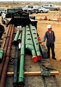
Downhole splitter systems, such as the Best Line System, require drilling an expanded hole size before the splitter can be set in the junction (Level 6S system). The 11/2° or 3°, wing-shaped junctions can be stacked so that opposing laterals or multiple pays can be drilled. There are two junctions loaded on the trailer closest to the man with the right-hand splitter pointing downhole towards the vehicles. The lateral junction split (closed ended) can be quickly drilled in preparation for lateral entry. (Fig. 9; photo by Steve Alexander, courtesy Mobil E&P Technology Center)Multilateral well systems now allow for a variety of junctions to be installed, depending upon the operators' needs as dictated by geologic, engineering, and economic considerations.
There are currently six distinct categories or levels of multilateral configurations (Fig. 1 [101,722 bytes]), each becoming progressively more complex. The levels, conceived and agreed upon by a consortium of operators and service companies (OGJ, Dec. 19, 1997, p. 75), allow interested parties to compare and categorize different concepts and degrees of difficulty.
![Fig. 1 [101,722 bytes]](http://images.pennwellnet.com/ogj/images/ogj2/9649jch01.gif)
TAML (Technical Advancement Multilaterals), a North Sea group dedicated to the advancement of multilateral technologies, was instrumental in the creation and adoption of this now-recognized industry standard.
This conclusion of a two-part series describes the classification system (Level 1 to Level 6) and tool types currently available for implementing the technology. It concludes with a discussion concerning multilateral system selection.
Level 1 systems
A Level 1 junction is one in which the main bore and lateral are uncased at the junction. There are likely over 1,500 such junctions installed to date within almost every hole size and configuration imaginable. These junctions are typically created with directional drilling assemblies and may be referred to as open-hole sidetracks.Normally, any service company that supplies downhole steerable tools can create a Level 1 system (Fig. 2 [37,508 bytes]). One of the most important concepts to understand in relation to the Level 1 (and higher) is the relationship between the radius of curvature and hole size.
![Fig. 2 [37,508 bytes]](http://images.pennwellnet.com/ogj/images/ogj2/9649jch02.gif)
Drilling a short-radius well, typically from vertical to horizontal in less than 100 ft, can only be performed in a 43/4-in. hole size or smaller. Larger tools, required to drill hole sizes of 6 in. or larger, are not able to "bend enough" to obtain the required radius of curvature.
Therefore, if the placement of the junction is placed in a pay zone 60 ft thick or less, it must be installed in a 43/4 in. or smaller hole size, or a well with sufficient deviation to allow the final curvature-from casing exit point to the desired location-to be positioned within the reservoir.
Level 2 systems
With a Level 2 junction, the main bore is typically cemented and the lateral is left open hole (barefoot). About 1,000 of these configurations are installed worldwide. To prevent the lateral from collapsing, the junction must be placed within a consolidated formation.There are two categories of Level 2 systems:
- Premilled windows
- Retrievable whipstocks.
![Fig. 3 [147,270 bytes]](http://images.pennwellnet.com/ogj/images/ogj2/9649jch03.gif)
Some companies also run an inner sleeve to prevent collapse during the cement operation. In conjunction with the window, either a casing nipple is run or some other method is used to orient the deflectors.
The biggest advantages to running premilled windows includes the ease at which bits can exit the casing and a reduction of large chunks of metal that is normally generated during a milling operation. Unfortunately, premilled windows can only be utilized on new wells, are difficult to install, and consume a great deal of time during cementation.
Almost all major service companies supply retrievable whipstock systems (Fig. 4 [186,616 bytes]). These can be obtained with some of the following options:
![Fig. 4 [186,616 bytes]](http://images.pennwellnet.com/ogj/images/ogj2/9649jch04.gif)
- One trip or multiple trip-Refers to the number of separate pipe trips needed to create the junction
- Anchoring device
- Packer on bottom
- Anchor on bottom
- Hydraulically set
- Mechanically set
- Set in casing or set in a special nipple profile run with the original casing string
- Run with extensions positioned between the anchoring device and whipstock. These are interchangeable so laterals can be cut at different depths.
There are now hollow-centered mills designed to core rather than mill. To ensure the mill starts cutting the casing rather than the whipstock, the starter mills utilize special deflectors integral to the tool. Changes have also been made to ensure the mill tracks the whipstock rather than exiting early or rolling off to the side.
However, with all these changes and improvements, window cutting is still more art than science. Utilizing correct bit weights, milling speeds, milling fluids, sweeps, and whipstock orientation are all learned through experience.
It is also important to ensure the planned window location is in a well-cemented position within the hole. In addition, the window location must be properly placed so the window is cut into the casing body rather than a collar.
Level 3 systems
Level 3 junctions have mechanical integrity in the junction. This may be accomplished mechanically by tying the lateral to the main bore or installing casing strings in both the lateral and main bore.One of the biggest problems in retrieving whipstocks is dealing with metal debris. Level 3 junctions are conventionally installed in heavy oil and unconsolidated sand reservoirs where there is a need to prevent sand from entering the well while preventing formation collapse.
To date, about 100 wells have been installed with Level 3 junctions worldwide. Typically, these junctions are placed either within the reservoir (many within branches) or where there is no need to shut off gas caps, along with other well bore isolation problems.
There are two basic types of Level 3 systems on the market (Fig. 5 [171,161 bytes]).
![Fig. 5 [171,161 bytes]](http://images.pennwellnet.com/ogj/images/ogj2/9649jch05.gif)
The first is where a window is cut into the casing and the whipstock is replaced with a deflector, allowing production to flow. A slotted liner or screen is then placed in the new lateral. Production from the main bore then passes through the deflector and into the slotted liner or screen of the upper lateral. Reentry into the well bore below the lateral is not possible.
The second system is where the liner is mechanically attached to the main bore. This requires running a mechanical latching system together with the primary casing string into the new well. Special tools are then used to cut the window.
Once the lateral has been drilled, a special tool is run on the end of a liner, serving to latch the lateral casing with the main bore. It is common to run a lateral casing string, one size smaller than normal, to accomplish this. The Sperry Sun (a Halliburton company) Lateral Tie-Back System (LTBS) and Secure Oil Tools Multilateral Production System (MLPS) are the most common Level 3 systems on the market.
Level 4 systems
A Level 4 junction is one in which both the lateral and main bore are cased and cemented ( Fig. 6 [225,775 bytes]). These junctions have mechanical integrity but are assumed to have no pressure integrity. From 1996 to present, about 50 Level 4 systems have been installed worldwide. The first installations encountered severe installation problems; however, recent success rates have been very high.![Fig. 6 [225,775 bytes]](http://images.pennwellnet.com/ogj/images/ogj2/9649jch06.gif)
Like the Level 3 systems, there are two basic methods used to create a Level 4 system. Both begin by placing a special whipstock in the main bore, cutting a window, drilling the lateral, and then cementing a liner in the lateral. At this point, the procedures and installation diverge.
For the first method, the liner from the lateral is removed from the main bore by using washpipe to wash over and recover the liner and whipstock, returning the main well bore to full ID. For the second method, it is necessary to drill a hole through the lateral liner and whipstock. In this method, one casing-size hole diameter is lost in the main well bore.
Baker Oil Tool Co.'s Root System and Sperry Sun's Retrievable Multilateral System (RMLS) are the most commonly provided washover methods. Halliburton Energy Services Inc.'s System 4500 is the most commonly provided drill-through method.
A simpler version of the Level 4 configuration consists of a hollow whipstock run in place of the conventional whipstock. To regain production from the lower lateral, it only becomes a matter of perforating through the casing and hollow whipstock. Washing over or milling through the lateral is not required, in effect becoming a much simpler and lower-cost alternative. However, this method precludes lateral reentry.
Level 5 systems
Level 5 junctions build upon the Level 4 system, expanded upon to include full pressure integrity at the main bore and lateral by running tubulars and isolation packers ( Fig. 7 [76,972 bytes]). These are relatively new systems, first introduced in 1996. To date, about 25 of these systems have been run worldwide.![Fig. 7 [76,972 bytes]](http://images.pennwellnet.com/ogj/images/ogj2/9649jch07.gif)
To build a Level 5 system, it is necessary to add packers above and below the main bore junction and lateral. Two separate tubing strings are run below a dual-packer configuration creating a junction with a separate tubing string devoted to and sealed in both the well bore and lateral.
These two separate completions may then be commingled above the dual packer in the main bore or through a "Y" block.
It is important to note that the two separate strings eliminate any pressure on the casing portion of the junction. If there is a leak in either one of these tubing strings at the junction, the junction will fail. If the pressure integrity is breached, and the junction is not set in a sufficiently strong formation, an underground blowout may occur or production may exit to the surface along the casing string annulus.
There are three primary suppliers and types of Level 5 systems: the Baker Root System, Sperry Sun RMLS, and Halliburton System 4500. As of October 1998, operators have installed about 10 wells with Level 5 systems.
Level 6 systems
Level 6 junctions are ones in which full pressure integrity is achieved with the main casing string. The pressure for the lateral casing string should be at least as strong as that of the main well bore. As of October 1998, only one test well in California has installed a Level 6 system.The most common system currently under development is the expandable metal systems (Fig. 8 [75,570 bytes]). In this case, a junction is manufactured at the surface, compressed, positioned downhole in an under-reamed section of the hole, and then reformed using either pressure or a swedge. Schlumberger Inc., Baker Oil Tools, and Rapid Tools S.A. are all known to be working on expandable systems.
![Fig. 8 [75,570 bytes]](http://images.pennwellnet.com/ogj/images/ogj2/9649jch08.gif)
Level 6S systems
Level 6S junctions (splitter) also achieve full pressure integrity with the main casing string. However, they are typically installed with unconventional casing and hole sizes (typically larger).There are two main types of Level 6S systems: those used at the surface and those installed downhole. There are over 60 examples of surface splitters as of mid-1998, while it is likely less than 10 downhole splitters have been run.
The benefit of these systems is that no milling or sealing of the junction is required downhole. All of these systems are manufactured so the engineer can inspect and perform tests on the system before it is run. This typically requires a larger hole size, but rig time is saved and complexity is reduced during the window generation and sealing operations.
The most common downhole splitters are the Baker/Marathon Splitter and the Bestline Co. MLWB (Multilateral Widebore) System. Both require larger holes to be drilled. The difference between them is that the Baker System splits at the bottom and the Bestline System splits off the lateral from the side. Therefore, the Bestline system allows junction stacking (Fig. 9).
The most common type of surface splitters is those supplied by Cooper Cameron Corp. and Marathon/ Kvaerner. Both are similar, allowing two wells to utilize the same conductor. If a 30-in. conductor string is run, it is possible to run either 133/8-in. or 95/8-in. casing strings. If a 36-in. conductor is run, it can accommodate two 133/8-in. surface casings. Typically both will allow 41/2-in. tubing/trees.
Casing reentry
There are two primary systems for depth control and lateral orientation:- Packer-based systems
- Nipple-based systems.
If the location of the window is lost, a window locator manufactured by Dresser, can be run on the bottom of a reentry sub.
Completion equipment
For the Levels 2 through 6 systems, every supplier has a system that allows a dual completion. Most also offer systems where the dual tubing strings can be run into the lateral. These systems are very reliable but add cost and complexity to multilateral operations.Commingled completion, using a common production tubing string, is the most common type of multilateral completion. Systems are available that allow window joints in the tubing to be placed across the lateral exit, and through the use of deflectors, allow coil tubing and wire line to be run into the well.
These window joints can also be equipped with chokes or blanking sleeves that serve to regulate the flow from the lateral. Standard chokes and plugs serve to regulate flow from the main bore.
The most common completion-regulating device is the sliding sleeve. It does not allow reentry but can easily be used to turn on and off production from the lateral. They may also be mounted with chokes to regulate flow.
Smart completion tools (surface controlled) may also be run but are typically very expensive.
System selection
There are four major areas to consider when selecting a multilateral system:- Lithology type in the junction area-If the formation is consolidated, a Level 2 or lower will be appropriate; if unconsolidated, a Level 3 or higher will be required.
- Pressure-seal junction requirement.
- None-Lowest-cost option
- Low
- High-Highest-cost option; may require development of special equipment.
- Re-enterability restrictions-First decide if it necessary to re-enter.
- It is necessary to have a rig on location and the well must typically be dead before using a work string/
- bent-joint assembly.
- If the operator chooses to wire line or coil tubing convey the workover tools without pulling tubing, the well must be equipped with special completion equipment.
- If the operator chooses to pull the tubing (work-over), the well must be dead and special equipment may have to be previously installed in the well.
- Commingled or separated flow design-The well may be equipped as a dual lateral, for example, and the production from two laterals treated separately as if they were two separate wells. Or the flow may be commingled downhole. Commingling from a completion and equipment point of view is simpler and less expensive. Production from each lateral may be estimated using a production log; however, commingled cross flows may occur.
Creating a sufficient drawdown at the junction will minimize cross flow.
Copyright 1998 Oil & Gas Journal. All Rights Reserved.