Slug flow control hinges on integrated operations

Mohamed Elhagar
PetroGulf Misr Co.
Cairo
Nour El-Emam
Al-Azhar University
Cairo
Mostafa Awad
Suez University
Suez, Egypt
Abu Zied Ahmed
Tarek M. Aboul-Fotouh
Al-Azhar University
Integrated slug-flow optimization can mitigate flow problems in a wide range of both offshore and onshore operating conditions. Slug flow is one of the most common flow states in horizontal and near-horizontal crude oil pipelines. Huge and fluctuating ratios of liquid to gas can severely affect production and in some cases lead to shut down or damaged topside equipment.
There is no one slug elimination and control method that can be used for all slug flow problems. Some are more general, such as the slug catcher. Others are simple, like fixed topside choking.
Slug flow optimization hinges on integration of production separator performance and pipeline performance. Such integration depends on installing automatic level control valves at the production separator inlets and adjusting integral and derivative control terms for the associated proportional integral derivative (PID) controller based on pipeline flow characteristics and separator operating conditions. At the same time, a minimum optimum PID output signal based on operating conditions prevents the control valve from completely closing and increasing pipeline back pressure to a point that leads to complete shutdown in the event of long-duration slug flow.
The slug flow optimizer has the following advantages in comparison with other slug control techniques:
• Low capital cost; $12,000 for a 6-in. control valve vs. $600,000 for a 300-bbl slug catcher skid package.
• Low installation and operating costs.
• Ease of installation; the feed control valve can be installed by hot tapping during any stage of operation without affecting production.
Olga software tested the integrated separator-pipeline system for use in actual oil and gas fields both offshore and onshore in Egypt, the North Sea, Colombia, Prudhoe Bay, and Saudi Arabia. The software evaluated the efficiency, advantages, and disadvantages of the integrated technique in overcoming slug flow problems and the effect of slug flow characteristics and flow parameters in the success of the integrated technique in controlling slug flow.
Background
Slug flow is unfavorable due to its unsteady nature, intermittency, and high-pressure drop. Slug flow can cause serious problems in the design and operation of two-phase flow systems. Automated control techniques using variable choke-valve sizes offer a new approach to controlling slug flow.
A variety of mechanisms can lead to slug formation. Problems associated with slugging include:
• High separator pressure, which can cause shutdown.
• Liquid overflow in the separator, which can lead to shut down and liquid carryover.
• Rupture due to sudden valve opening, which can damage process equipment.
• Overload on downstream equipment.
• Pigging problems related to pig velocity and pipeline geometry.
• High frictional-pressure drop.
• Fatigue caused by repeated impact, which can cause mechanical failure.
Slug mitigation
Pipeline layout and sizing, decided early in a system’s design, can help control slug formation and associated problems. Once layout and sizing are determined, however, slug remediation options are limited. Fixed topside choking can prevent severe slugging by choking the flow at the top of the riser. Increasing flow line pressure reduces the operating envelope that creates slug-flow, eliminating it above a certain pressure. Increasing flow velocity by increasing production or reducing the pipeline size is also beneficial in addressing severe riser slugging.1
Riser-base gas lift injects gas at the riser base to continually lift liquid out of the riser, preventing its build up and the subsequent restriction of gas flow. Gas lift in the wells can also be used to prevent slugging in the flow lines and riser. Choking and gas lift require a lower degree of choking and smaller gas volumes to eliminate severe slugging.
A slug suppression system developed by Royal Dutch Shell separates fluids into gas and liquid streams, controlling the liquid level in the separator by throttling the liquid stream and controlling the total volumetric flow rate by throttling the gas stream.2
Other solutions include modifying flow line layout or riser base geometry to avoid dips. Pigging can be used to control hydrodynamic or severe slugging in gas-condensate lines by continually removing liquid accumulated in the flow line before slugging becomes a problem. Subsea separation is another method for addressing severe slugging problems associated with deepwater production.
Connecting the riser to the downward inclined segment of the pipeline with a small diameter conduit can transfer the gas from the downward-inclined segment to the riser, while slug catchers can be considered a type of a two-phase gas-liquid separator handling large gas capacities and liquid slugs.
Automatic control
Automatic control methods (feed forward control, slug choking, active feedback control), use pipeline information to adjust available degrees of freedom (pipeline chokes, pressure) to reduce or eliminate the effect of slugs in the downstream separation and compression unit.3 One the first practical applications of a slug controller was implemented on the Dunbar pipeline, a 16-in. OD multiphase pipeline between the Dunbar field and the Alwyn platform in the North Sea.4 Slug flow was controlled using the choke-valve as the manipulated variable of riser base pressure.
An acoustic slug-detection system using feed-forward control monitors slug characteristics (slug length, slug velocity, and fluid density) and detects slugs roughly 2 min before they arrive at the first-stage separator or downstream equipment.5 It is up to the operators to handle the information and take appropriate action. This method depends on accelerometer sensors that measure vibrations in the pipeline caused by slugs. The vibration frequency generated during slugging differs from the vibration frequency caused by the gas.
In 2001, ABB Corporate Research in cooperation with Scandpower AS developed active feedback control to overcome slug flow problems and tested it on the Hod-Valhall 13-km multiphase pipeline, in addition to simulations performed using Olga 2000.6 Topside measurements can be used to stabilize flow, but further work is needed.7
Adjusting riser base-pressure with a slow primary loop controlling valve opening via integral action can detect slugs as well.8 Riser slugging in pipelines also can be stabilized using simple control systems, but the type and location of measured input to the controller is critical.9 Controller tuning has a large influence on results of severe slug control.10
Installing a subsea choke valve close to the riser base or installing a choke valve at the topside had the same effect on slug control, but a wellhead valve is not suitable for slug control.11 Existing anti-slug control systems are often not operating because of robustness problems. The closed-loop system becomes unstable after some time, for example, because of inflow disturbances or plant changes. Operators turn off the controller and instead use manual choking when the control system becomes unstable.11
Slug flow optimizer
Slug flow optimization depends on continuous integration between pipeline performance and separator performance and uses the pipeline as a buffer for slug flow. Slug accumulation can be prevented with little or no new equipment. Optimization offers a cost-effective solution operating near the boundary conditions that would normally cause slug flow.
Optimization depends on installing an automatic level-control valve at the inlet of the production separator. This integrated system was tested by Olga 2015,1 software with the slug tracking module ‘On’ and the model for the valve selected as ‘Hydrovalve’. The model was developed for actual onshore and offshore oil and gas fields in Egypt, the North Sea, Colombia, Prudhoe Bay, and Saudi Arabia.
PID controllers were tuned in each case by trial and error, and three proportional, integral, and derivative control terms were adjusted to apply accurate and optimal control based on pipeline flow characteristics and operating conditions of the separator and to control back pressure in the pipeline. Setting the PID controllers’ minimum output signal in each case prevented complete closure of the control valve and resulting increased pipeline back pressure, avoiding complete shut down in case of long slug flow durations. Olga models were used to evaluate the efficiency, advantages, and disadvantages of slug flow optimizers in overcoming slug flow problems.
Validation
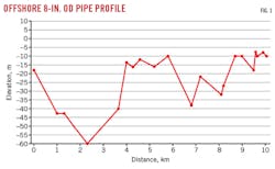
Validation checked the Olga 2015 software against actual slug flow data. The data were collected from slug flow on an 8-in. OD inclined offshore pipeline in Egypt (Fig. 1) during production evaluations using calibrated devices. Table 1 shows Olga’s absolute error as 0.06%, with 100% accuracy in predicting slug flow’s existence.

Six cases collected from five oil and gas fields in different areas provided the basis for evaluating the effectiveness of slug flow control achieved by installing an automatic level-control valve at the inlet of each production separator.
Egypt
The slug-flow data collected from an 8-in. OD inclined offshore pipeline linking the Tawila wellhead platform to the production separator at WP-A platform offshore Egypt provided the basis for two cases. Tawila wellhead is 10.07 km from WP-A (Fig. 1). Oil flow ranged from 129 to 823 b/d and GOR ranged from 800 to 2,250 scf/bbl.
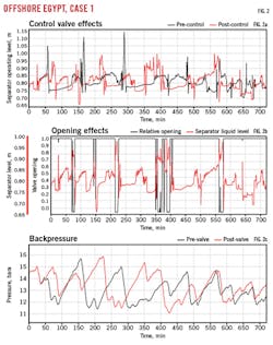
• Case No. 1. Flow rate was 823 b/d, with 43% bs&w and GOR of 1,244 scf/bbl (Table 2). Fig. 2a shows the separator operating level before and after putting the feed control valve in service. Before the feed control valve pipeline slug flow affected the separator’s stability, slugs reaching more than 75% of the separator’s inner diameter, big enough to lead to carryover or total shut down.
The feed control valve entered service with an adjusted minimum output signal of 0.05% open to prevent it from completely closing and increasing pipeline backpressure. In addition to tuning the PID-controller parameters to apply accurate and optimal control of the feed valve opening, the feed control valve gave good control performance of the separator’s level, keeping it less than 65% of inner diameter.
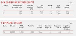
Fig. 2b shows the feed control valve action’s effect on separator level. Fig. 2c shows the pipeline’s backpressure before and after putting the feed control valve in service. Fig. 2c also demonstrates that the pipeline’s backpressure after putting the feed control valve in service was controllable.
• Case No. 2. In this case, Olga software modelled the offshore pipeline and production separator with the flow rate at 127 b/d, 50% bs&w, and GOR = 1,968 scf/bbl. Pipeline and separator performance was analyzed with and without a feed control valve at the production separator inlet
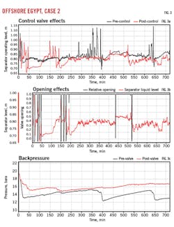
Fig. 3a shows separator operating levels before and after putting the feed control valve in service. Before installation the separator operating level was unstable and changed many times between 0.7 m and 1.5 m. After putting the feed control valve in service, adjusting the minimum output signal of the control valve to 0.05, and tuning the PID controller, the feed control valve stabilized and kept the separator’s operating level at less than 65%. Fig. 3b shows feed control valve action with separator level and Figure 3c shows feed control valve success in stabilizing pipeline backpressure.
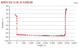
North Sea
The third case was from a ConocoPhillips-operated North Sea field.12 The flowline is a three-phase, 18-in. ID pipe running 3.7 km from a wellhead platform to a central processing platform. The line drops about 6 m over the last 3 km before flowing up a 130-m riser (Fig. 4). The pipeline exhibited severe riser slugging and hydrodynamic slugging, causing separation and water handling problems on the platform.
The oil flow rate was 36,000 b/d, GOR = 167 scf/bbl, with a water cut of 48.4%. Olga modelled pipeline and separator performance with and without a feed control valve. The production separator dimension was 11 × 3.5 m.
Fig. 5a shows separator operating levels before and after putting the feed control valve in-service. In normal operation and before using the feed control valve, riser slug flow affected the separator’s operating stability as slug frequency was very high and the separator level would change dramatically in short periods of time from 2 m to 3.4 m, more than 97% of the unit’s inner diameter. Putting the feed control valve in service, however, with the same standard adjustments to control valve signal and PID controller parameters used in Cases 1 and 2, stabilized the separator’s operating level at 2.6 m while also reducing slug frequency (Fig. 5a).
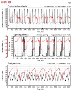
Fig. 5b shows feed control valve action with the separator level and Fig. 5c shows the pipeline backpressure before and after putting the feed control valve in service. The figure shows a slight increase in pipeline backpressure, negligible compared with the newly attained complete control of slug flow and protection from total shut down.
Colombia
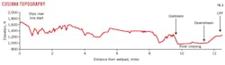
The Cusiana oilfield, containing 1.6 billion barrels of 35° API oil, lies in the Eastern Cordillera of the Andes Mountains, Colombia. Current production rates are roughly 180,000 b/d, with a GOR of 1,400-2,000 scf/bbl and little water.13 The wells are connected to a central processing facility (CPF) via a complex network of multiphase flowlines ranging in diameter from 8 to 20-in. and in length from 0.4 to 12.5 miles. At the end of the flowline network, a manifold system connects to two finger-type slug catchers feeding four parallel 40,000 b/d processing trains.
Table 3 shows slug flow data collected from one of the multiphase flowlines, a 20-in. OD inclined onshore pipeline from T-Q wellhead to a CPF about 20 km away (Fig. 6). Oil flow rate was 26,000 b/d with GOR of 1,400 scf/bbl.
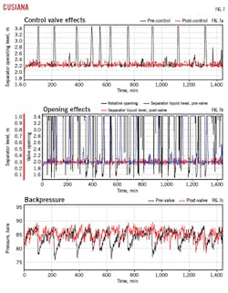
Olga software modelled the pipeline and production separator. With the feed control valve turned off slug frequency was high and separator levels swung from 55% to more than 97% of diameter (Fig. 7a). After putting the feed control valve in service and tuning PID controller parameters, the feed control valve succeeded in stabilizing separator level at 60% of diameter (Fig. 7b). Fig. 7c shows that the feed control valve had little effect on pipeline backpressure.
Prudhoe Bay
Measurement of flow rates, inlet and outlet pressures, and temperatures on a 3-mile, 16-in. OD flowline in Prudhoe Bay field, Alaska, provided the basis for the fifth case (Fig. 8). Gamma densitometers monitored flow patterns, determined mixture densities, and slug characteristics. Oil flow rate was 64,986 b/d with GOR of 804 scf/bbl (Table 4).
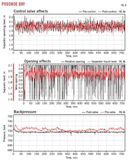
The high flow rate and pipeline operating near capacity prevented slug flow buffering. The feed control valve failed to control the slug flow or reduce its effect on the production separator (Fig. 8a).
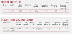
Fig. 8b shows pipeline back pressure before and after putting the feed control valve in service, illustrating the lack of effect. Fig. 8c shows feed control valve positions and separator level.
Saudi Arabia
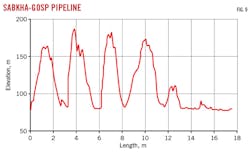
Oil production in Saudi Arabia includes a complex multiphase pipeline network. The pipelines cross hilly terrain with sand dunes rising as high as 200 m, transporting wet crude to a gas-oil separation plant (GOSP).14
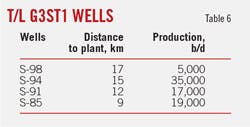
Data was collected from the 17.4-km, 20-in. OD trunkline connecting Sabkha with GOSP-3 (Table 5). Four wells fed this pipeline (Fig. 9, Table 6), which exhibited terrain-induced slug flow.
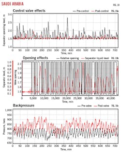
Olga simulation found high slug frequency and a separator operating level ranging from 1.5 to 2.8 m, more than 93% of diameter and a shutdown risk (Fig. 10a). Turning on the feed control valve and tuning its parameters stabilized separator levels at 1.5-1.8 m or a maximum of 60% of separator inner diameter. Fig. 10b shows a slight increase in pipeline backpressure after turning on the feed control valve and Fig. 10c the feed control valve action and separator level.

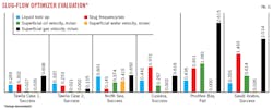
Table 7 and Fig. 11 summarize the case study results. A combination of parameters led to success in controlling slug flow, liquid hold up and superficial velocity being key among them.
References
1. Sagatun, S.I., “Riser slugging—a mathematical model and the practical consequences,” SPE Production & Facilities, Vol. 19, No. 3, August 2004.
2. Kovalev, K., Seelen, M.G.W.M., and Haandrikman, G., “Shell Global Solutions International B.V. Vessel-Less S3: Advanced Solution to Slugging Pipelines,” SPE Asia Pacific Oil and Gas Conference and Exhibition, October 18-20, 2004, Perth.
3. Mokhatab, S., Towler, B.F., and Purewal, S., “A Review of Current Technologies for Severe Slugging Remediation,” Petroleum Science and Technology, Vol. 25, No. 10, October 2007, pp. 1235–1245.
4. Courbot, A., “Prevention of Severe Slugging in the Dunbar 16-in. Multiphase Pipeline,” Offshore Technology Conference, May 5-8, 1996, Houston.
5. Dhulesia, M.B. and Romanet, T., “Field Installation of an Acoustic Slug-Detection System,” SPE Annual Meeting, Oct. 22-25, 1997, Dallas.
6. Havre, K. and Dalsmo, M., “Active Feedback Control as the Solution to Severe Slugging,” SPE Annual Technical Conference and Exhibition, Sept. 30-Oct. 2, 2001, New Orleans.
7. Olsen, H. “Anti-slug control and topside measurements for pipeline-riser system,” Master’s thesis, Norwegian University of Science and Technology, 2006.
8. Hauge, E. and Morten, O., “Modeling and Simulation of Anti-slug Control in Hydro Experimental Multiphase Flow Loop,” Master’s thesis, Norwegian University of Science and Technology, 2007.
9. Storkaasa, E. and Skogestad, S., “Controllability analysis of two-phase pipeline-riser systems at riser slugging conditions,” Control Engineering Practice, Vol. 15, 2007, pp. 567-581.
10. Sivertsen, H., Storkaas, E., and Skogestad, S., “Small-scale experiments on stabilizing riser slug flow,” Chemical Engineering Research and Design, Vol. 88, No. 2, February 2010, pp. 213-238.
11. Jahanshahi, E., “Control Solutions for Multiphase Flow Linear and nonlinear approaches to anti-slug control,” Ph.D thesis, Norwegian University of Science and Technology, 2013.
12. John, T. and Bansal, K.M., “Simulation of Slug Flow in Oil and Gas Pipelines Using a New Transient Simulator,” Offshore Technology Conference, Apr. 30-May 3, 2012, Houston.
13. Hill, T.J., Fairhurst, C.P., Nelson, C.J., Becerra, H., and Bailey, R.S., “Multiphase Production Through Hilly Terrain Pipelines in Cusiana Oilfield, Colombia,” SPE Annual Technical Conference and Exhibition, Oct. 6-9, 1996, Denver.
14. Alvarez, C.J., “Wet Crude Transport Through a Complex Hilly Terrain Pipeline Network,” SPE Annual Technical Conference and Exhibition, Oct. 3-6, 1999, Houston.
The authors
Mohamed Elhagar ([email protected]) is a process engineer at PetroGulf Misr Co. with more than 15-years of experience in the oil and gas industry as a process, flow assurance, and process safety engineer for offshore and onshore oil fields. He holds an MS in comparative study of two-phase flow in inclined pipelines and a BS in chemical and petroleum refining engineering from Suez Canal University, Egypt.
Nour Ahmed El-Emam is a professor of petroleum engineering in the mining and petroleum engineering department at Al-Azhar University, Cairo. El-Emam holds a PhD in petroleum engineering from the Technical University of Heavy Industries, Miskolc, Hungary.
Moustafa El Sayed Awad is a chemical and petroleum refinery professor at Suez University, Suez, Egypt, with more than 35 years in the oil and gas industry as a project and operation consultant and part-time instructor. Awad holds a PhD in chemical engineering from Ecole Central de Lyon, Claude Bernard Universite, France.
Abu-Zeid Ahmed El-Sayed is associate professor in the petroleum department’s faculty of engineering at Al-Azhar University. He has worked as lecturer in petroleum engineering at British University, New Cairo Academy, Port-Said University, and Suez Canal University. He has also worked as senior petroleum engineer in the oil production department of Agiba Petroleum Co. He was awarded BS (1987), MS (1992), and Ph.D (1998) degrees in petroleum engineering by Al-Azhar.
Tarek M. Aboul-Fotouh is an associate professor of petroleum engineering in the mining and petroleum engineering department at Al-Azhar University. He is also an associate professor of chemical engineering at the British University in Egypt, and an associate professor in the petroleum engineering department at the Future University in Egypt. He served as chairman of the Second International Conference and Expo on Oil and Gas, October 2016, Rome. He is also a member of the Society of Petroleum Engineers (SPE) and the American Institute of Chemical Engineers (AIChE). Aboul-Fotouh holds a Ph.D in chemical engineering from Azerbaijan State Oil Academy in Baku.