Revised characteristics curve optimizes jet pumping
A revised characteristics curve provides a method for optimizing jet pump designs by taking into account the influence of solution gas and the different densities of the power and produced fluids.
For jet pumps in a conventional pipe string, the pump provides the only path for both oil and gas, and solution gas will influence pump operation whenever the pump intake pressure is less than the saturation pressure.
If the jet pump can produce the same volume of the gas-liquid mixture as the pure liquid, then average density of the produced mixture can be calculated from the gas-liquid ratio at the pump intake, and this provides the basis for a revised characteristics curve with solution gas.
Also, the difference in the density between the power and produced fluids will influence the pump characteristics curve.
Jet pumps
Jet pumps interest oil field operators because the pumps have no moving parts and can be replaced in a well without the need to pull sucker rods or tubing. Operators often install these pumps in deep or deviated wells and in wells producing a viscous fluid.
Compared to sucker rod pumps, fewer jet pumps have been run in wells and less research is available on the effects of gas on the pumps.
As with other pumping systems, operators base the pump design on the capacity of a reservoir's inflow performance relationship (IPR) curve and a nodal analysis method that takes into account the oil reservoir, tubing and casing size, surface facilities, and other influences on fluid flow. In designing this system, one needs to coordinate all of these aspects.
Power fluid mixes with formation fluid and the mixture at the pump outlet needs to be at a sufficient pressure to reach the surface. In a conventional tubing installation, all fluid will pass through the jet pump.
Pressure variations in the jet pump are quick and complex. Changes in solution gas in the pump may influence cavitation in the flow, but this cavitation differs from that caused by the discharge pressure at the jet pump being less than the saturation pressure. Because of the free gas, gas will occupy a part of jet pump's volume and influence the pump efficiency.
Solution gas calculation
When Brown discussed solution gas in jet pumping systems, he assumed a jet pump can produce the same volume of the gas-liquid mixture as the pure liquid.1
In calculating pump efficiency, one first assumes the jet pump's flow ratio (M) and then obtains the power fluid rate (q1) from the rate of the produced fluid (q3).
According to gas-liquid, two-phase vertical pipeline flow theory, one calculates the pressure head ratio (H) from the pressure (p1) of the power fluid and the pressure (p2) of the mixture at the pump discharge. The corresponding M is found from the pump's standard characteristic curve.
The volume efficiency can be calculated based on the GOR of the output fluid at the pump intake. M is a multiplier of the volume efficiency. After obtaining the first revised M, one does iterative calculations until a more accurate M and H is obtained for the conditions at the pump.
These calculations for solution gas for a jet pumping system mainly deduce the pump's working condition on the basis of the jet pump, tubing, casing, surface equipment, power fluid, and formation fluid influx. The calculation avoids variations of the pump's working behavior with gas effects.
Revised characteristic equation
A characteristic function is the main basis for a jet pump's design. The characteristic function that Brown provided is only applicable to a system in which power fluid and output fluid density is the same.
To consider the influence that power fluid of various densities has on jet pumping system, Wang Changbin made use of energy conservation theory, and obtained the jet pump characteristic equation that is suitable for an anisodensity system.2 He also analyzed the influence of density ratio on a jet pump's hydraulic characteristics.
A combination of Brown's assumptions of a gas's effects on a jet pumping system with the jet pump's working characteristics in an anisodensity system provides a method of using a revised pump characteristic curve to calculate gas effects in jet pumping.
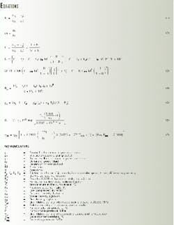
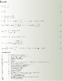
Equation 1 (see equation box) defines the dimensionless pressure ratio (H), and Equation 2 defines the dimensionless density ratio in the anisodensity system.
Based on the energy conservation theory and Lorenz's mixing losses model, Equation 3 shows the jet pump's working characteristic, revised from Brown's method, that is applicable for anisodensity system.
After substituting the pump's area ratio, friction-loss factor, power fluid used, and formation fluid density in Equation 3, one obtains pressure head ratio (H) and flow ratio (M). These values describe a jet pump's working behavior, and from this equation one can draw a jet pump's characteristic curve.
According to Brown's assumption, jet pumps in a well with solution gas can produce the same volume gas-liquid mixture as the pure liquid. In Equation 2, the r3 can be thought of as a mixture density of gas and liquid, so that from this, one can determine a jet pump's characteristic equation for pumping liquid with gas.
Equations 4 and 5 calculate the p3 at the intake of jet pump.
Gas in solution will evolve when the pump's intake pressure (P3) is less than saturation pressure, and then Equation 4 defines the gas-liquid ratio (R3).
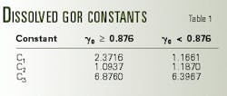
Because the gas density is much less than liquid density, the gas term in Equation 5 can be neglected. The dissolved GOR in Equation 4 is calculated by Equations 6 and 7.3
Table 1 lists the constants for these equations.
Application
As an example, consider a well with a 925 kg/cu m crude oil density, 1,020 kg/cu m water density, 50% water cut, 1,000-kg/cu m power fluid density, a 5 produced GOR, 6.92-MPa saturation pressure, and a 0.774 gas relative specific gravity.
Working characteristics (Table 2) for the jet pumps are Kj = 0.15, Ks = 0, Kt = 0.28, Kd= 0.10, and R = 0.41. The pump intake pressure is 4, 5, 6, and 7 MPa, respectively, and the pressure head ratio is 0.45.
Table 2 shows that gas has an obvious influence on the pump's working behavior. As suction pressure increases, pump entrance gas-liquid ratio decreases, dimensionless density ratio increases, pump's volume flow ratio decreases, pump efficiency decreases, and liquid volume flow ratio increases.
Although the decrease of pump intake pressure will increase pump efficiency, pump efficiency results from the pressure-head ratio multiplied by the volume flow ratio (including gas). Only the liquid volume flow ratio has practical importance, and it will increase as the intake pressure increases.
When pump intake pressure is greater than saturation pressure, no solution gas will evolve, and the pump characteristic curve is the same as when pumping pure liquid.
If a well's water cut is less, or production GOR is great, the solution gas will affect pump working condition significantly.
To decrease the influence of solution gas on the pump, one should increase the submergence depth of the pump, so that the pump intake pressure approaches saturation pressure.
When pump intake pressure is less than saturation pressure, the influence of gas on the jet pump characteristics cannot be neglected, and the design requires one to revise the pump characteristic equation.
References
- Brown, K.E., The Technology of Artificial Lift Methods, Volume 2a. PennWell Publishing Co., Tulsa, 1980.
- Chanbin, Wang, et al., "Hydraulic Characteristics of Jet Pumps in the Non-isodensity System," Journal of DaQing Petroleum Institute, Vol. 21, No. 2, 1997.
- Chen, Yuanqian, Calculating Method of Reservoir Engineering, Petroleum Industry Publishing House, Beijing, 1994.
The authors
Wang Kuisheng is professor and dean of the department of mechanical and electronic engineering in the Beijing University of Chemical Technology. Wang Kuisheng holds a PhD from the University of Petroleum, China.
Tian Zhongqiang is a senior engineer at the Dongxin production plant of Sheng* Petroleum Administration Bureau, China. He is a graduate of East China Petroleum Institute.


