Gas line along Osaka Bay uses shield tunnel under seabed
Osaka Gas Co. Ltd., Osaka, this month is commissioning a 21-km gas transmission pipeline across an area of Osaka Bay from the Senboku LNG terminal to the Hokko Compressor, distribution station to meet increasing gas demand of the Osaka district, the second largest metropolitan area in Japan.
The line has 7 MPa maximum allowable operating pressure (approximately 1,100 psi), 750 mm (30 in.) OD, and 19 mm (0.750 in.) WT. It was built in a shield tunnel under the seabed.
The company encountered several design and construction problems in devising measures to counter subsidence of reclaimed land in the bay and anticipated seismic activity.
Among three proposed pipeline routes (onshore, offshore, and across reclaimed land in the bay), Osaka Gas selected the latter route for the following reasons:
- Administrators for both road and police do not allow pipeline construction because of the heavy road traffic in the onshore densely built-up area.
- The pipeline could not be constructed on the seabed because of possible blocking of the busy sea traffic in Osaka Bay, one of the largest trading ports in Japan.
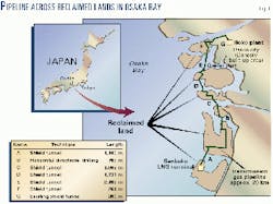
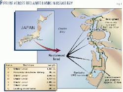
- Pipeline construction across reclaimed bay land by using a shield-tunnel and partly horizontal directional drilling does not interfere with sailing routes. Fig. 1 shows the selected route across six parcels of reclaimed land in Osaka Bay.
Following are the technical challenges for the construction:
- Devise measures against subsidence of the reclaimed land.
- Improve antiseismic performance.
- Improve operation and reduce costs in on site welding and on site coating.
- Devise and install an appropriate maintenance system.
Measures against subsidence
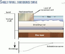
The load of reclaimed soil compresses the clay layer beneath the original seabed (Table 1). Differential subsidence between the reclaimed land and the seabed is caused by consolidation of the clay layer (Fig. 2).
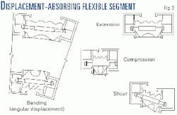
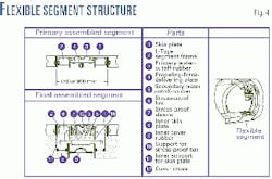
A flexible segment of the shield tunnel can sufficiently absorb the forces caused by the differential subsidence. The segment also protects against the destructive force of the subsidence.
The flexible segment is capable of absorbing the bending, shearing, and tensile-compressive forces exerted on it (Fig. 3).
Table 2 shows the allowable displacements of the flexible segment. The segment uses special sealing rubber to make a pressure-tight connection against the water and earth pressures of 40 m under the seabed (Fig. 4).
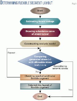
Fig. 5 shows how the layout of flexible segments is determined.
A soil survey estimated the rate of sinkage of the clay layer under the shield tunnel and vertical shaft. Data for the estimated sinkage allow the subsidence curve of shield tunnel to be drawn.
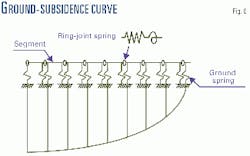
The tunnel is transformed to a calculation model, with ground springs, joint springs, and ground loads, that corresponds to the subsidence curve produced by computer analysis (Fig. 6).
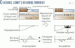
The analyzed bending moment of each joint is compared with the allowable bending moment in the process of the computer analysis. Joint springs with an analyzed bending moment of more than the allowable bending moment should replace the joint hinges (flexible segment) with a bending moment of zero.
In this case, the number of the flexible segments should be kept to a minimum. Locations of the flexible segments are determined after computer analyses are repeated until the bending moment of every joint comes to less than the allowable (Fig. 7).
The shield tunnel must have a sufficient antiseismic strength in the joints between the vertical shaft and the shield tunnel and the joints of each segment comprising the shield tunnel.
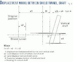
The vertical shaft and the shield tunnel independently move in different axial displacements in case of an earthquake (Fig. 8; Table 3).
The flexible segment, which can absorb the difference of the displacement, protects the shield tunnel against the seismic-destructive power.
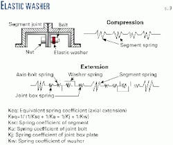
The shield tunnel consists of segments and segment joints. For the computer analysis, a shield tunnel structure is a uniform continuous beam with the stiffness equal to the actual shield.
The joint material of each shield segment is an elastic washer. The washer at the segment joint, which is treated as a spring in the structure strength analysis, performs as a safety device to mitigate the axial tensile force caused by an earthquake (Fig. 9).
Automated welding, coating
The diameter of the shield tunnel was kept at minimum workable space to reduce construction costs.
The 750-mm pipeline had to be constructed in a space only 2.4 m in diameter.
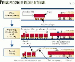
Osaka Gas realized cost reduction and improved construction quality by using on site automatic welding and automated coating application in the narrow workspace (Fig. 10).
The automatic three-head gas metal arc (GMA) welding machine with automated inner clamp allows reduction of the welding time by as much as half.
The automatic welding requires only 3.5 hr compared with conventional manual welding, which requires 7 hr.
Two weldings a day realized a considerable reduction of welding time. The improvement of the work progress led to the cost reduction.
The on site automatic electrical coating system using a shrinkable tube safely performed the coating without use of a gas torch.
The on site automatic coating system gives excellent coating performance with no air voids that are harmful for long-term corrosion protection; the shrinkage process is conducted under quasi-vacuum condition.
Maintenance system
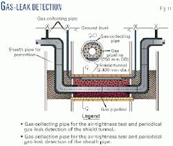
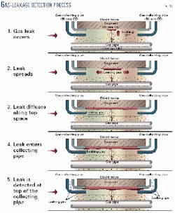
The gas-leak-detection method in the shield tunnels under the seabed was verified by a gas-leak-detection test.
The outer space of pipeline in the shield tunnel is filled with sand except for the narrow top space.
The gas-collecting pipes are led from both the end of the shield tunnel and the vertical shafts to the ground-surface top ends in hand holes.
Gas leaking from the gas transmission pipeline can be detected at the top end of gas-collecting pipes after diffusing along the narrow top space filled up with water (Fig. 11).
The leaking gas from the gas pipe is detectable as it reaches the collecting pipe through the process shown in Fig. 12 in case of gas leakage.
The gas transmission pipeline, whose outer space is filled with sand, has almost the same environment as a common buried pipeline.
Both pipelines will be corrosion-protected by a rectifier to maintain their integrity.
And a pipeline coating holiday monitoring system utilizing the rectifier will be also applied to the gas transmission pipeline across the Osaka Bay to identify the damaged pipeline section in case of coating damage. F
The author
Takashi Aihara is a manager of the construction team in the central transmission office of Osaka Gas Co. Ltd. He has 21 years' experience in design and construction of high-pressure pipelines and holds a BS in civil engineering from Kyoto University.
