Improved hot gas sampler allows for more-precise analysis
Chemopetrol AS has improved its hot-gas sampling equipment at its Litvinov, Czech Republic, ethylene plant, giving it more-accurate yield data with which to plan its ethylene operations.

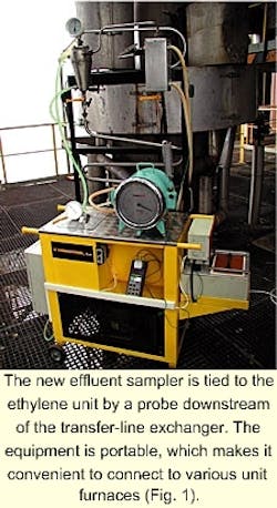
Equipment tests show the new sampling equipment (Fig. 1) has improved temperature stabilization and back temperature regulation. The new system has a lower pressure drop than the original sampling device and thus suppresses undesired pressure pulses.
Unlike the old process, the new sampling process allows a good separation of the pyrolysis oil from the dilution water and pyrolysis naphtha in the first cyclone. This allows easy separation of the water and pyrolysis naphtha into two immiscible phases later. The supplementary distillation of imperfectly separated fractions contributed to imprecise determinations of product yields.
New sampling bags, rather than traditional glass tubes, permit direct preheat of the gas above the boiling point of the heaviest component. This ensures homogenization of pyrolysis products for the subsequent gas chromatography analysis.
The portability of the equipment allows the plant to carry out reliable measurements on different pyrolysis furnaces in a short amount of time.
Sampling systems
The optimization of cracking products sampling is an important task at Chemopetrol. Previous sampling prototypes insufficiently separated pyrolysis oil, pyrolysis naphthas, and dilution water.
Raised pressure pulses in the sampling equipment also negatively influenced the sampling. Additionally, the glass sample tubes used to transport the gaseous product to the gas chromatography analysis were unsuitable because they were fragile, had leaking valves, and had a fixed volume.
Chemopetrol's Litvinov ethylene cracker treats both gaseous and liquid feedstocks, such as ethane, LPG, naphthas, atmospheric gas oils, and hydrocracker residues. This wide variety of feeds yields various cracked products.
The wide range of feeds and products also makes research of optimum plant regimes, complex planning of pyrolysis furnaces operation, and optimum feedstock blending inevitable.
Online analyzers and full-scale experiments provide information for the planning, control, plant optimization, and testing of new or revamped furnaces.
The sampling points for online analyzers are usually behind the cracking coils in an oil quench area where the temperature is low, that is, less than 200° C. Here, the heavier hydrocarbons are liquefied and cannot be separated for a materials balance.
The analyzers sample every 8 min. and determine five components: methane, ethane, ethylene, propane, and propylene. The results are used to compute the propylene to ethylene ratio.
Significant systematic errors, for example, owing to the unsteady state of pyrolysis coils during the measurements, often occur in the analysis results.
Unlike online monitoring, full-scale experiments are based on the direct sampling from cracking coils (hot gas sampling). A cooling system separates the reaction mixture of hydrocarbons and dilution steam afterwards to gaseous and liquid fractions. Gas chromatography separately analyzes the liquid and gaseous products.
The individual sampling devices differ in the separation methods1-6 they employ. A fundamental task of full-scale experiments is to locate a sampling point. The cracking effluent is completely in the gas phase upon leaving the radiant coil.
Although this is an ideal measurement to have, it is difficult to place a sampling probe in the furnace outlet because the gas temperature exceeds 800° C. Furthermore, hydrocarbon reactions occur from the nearly adiabatic part of the cracking coil to the transfer-line exchanger.
For these reasons, the sampling probe is in the transfer-line exchanger outlet. The operators consider the reaction-mixture composition behind the transfer-line exchanger as the actual product distribution of the cracking reactor.
New sampling process
The new sampler has a continuously operating separation unit. The sampling probe is mounted on the outlet of the transfer-line exchanger, the same location as the probe of the old sampling system.
The temperature of the effluent reaction mixture reaches 450-630° C., high enough to ensure that all products are in the gaseous phase.
The sampling probe withdraws a representative fluent sample of the reaction mixture. The probe is specially designed for the uptake of effluent gases from the center of the pipe on the outlet of transfer-line exchanger.
The pyrolysis effluent gases from the sampling probe go through several cooling stages to separate the gas and liquid phases. The sampler accumulates the liquefied pyrolysis products and removes the gaseous fraction from the system through a gas meter.
Fig. 2 shows the fractionation of pyrolysis products in the sampling system. When valves V1 and V2 are open, hot pyrolysis products head to the cyclone, which has a heating jacket (U1). A silicone oil preheats the cyclone to keep the gas temperature in the cyclone outlet (TIC 01) at a steady level (110-120° C.). It thereby separates the pyrolysis fuel oil.
The mixture of hydrocarbons and water then goes to the next cyclone (U2), which is equipped with a cooling jacket and cooled by a mixture of ethanol and water. A considerable part of pyrolysis gasoline and process water accumulates here.
The temperature of the gas at the outlet of the second cyclone (TI 01) is about 40° C. The gas then passes through air cooler E1 and cooler E2 to the third cyclone (U3), in which the residue of process water and pyrolysis gasoline is captured.
Finally, the gas stream passes through the filter (F1) and the wet gas meter (FI 01) to a gas holder for safe disposal. The gas meter is equipped with a simple thermometer (TI 03) and a liquid U-manometer (PDI 01).
The sampling starts when the temperature in the sampling system is steady. Operators adjust the gas flow through the wet gas meter for 600 l./hr and control it with valve V2.
The sampler collects three samples of gas from the system in evacuated sampling bags made from a polyvinyl fluoride film. The sampling bags are equipped with a jointing valve and septum.
The prior glass sampling tubes could not be heated for safety reasons, which included pressure increases and cock leakages.
The sampling into the sampling bag is performed when Valve V5-01 is open and Valve V5-02 is closed. The sampling is finished when 300-600 l. of gas have passed through the wet-gas meter. After that, the contents of cyclones and filter are removed.
Sample analysis
Chemopetrol uses gas chromatography to analyze the hydrocarbon gases, pyrolysis gasoline, and pyrolysis-fuel oil samples.
It uses the chromatograph HP 5890 II for gas and gasoline analysis. A thermal conductivity detector determines hydrogen and methane contents, and a flame ionization detector analyzes the other hydrocarbons.
The gas analysis uses the double-column system (Molsieve 5A capillary and Al2O3/KCl capillary), and the gasoline analysis uses the HP-PONA capillary. Chemopetrol uses the Analytical Controls SIMDIST method, which uses the gas chromatograph (HP 6890) with the DB-HT SIMD metal capillary to analyze the pyrolysis-fuel oil.
- Gas-effluent analysis. Chemopetrol preheats the gases in the sampling bags above the boiling point of the heavier components to ensure good homogenization of pyrolysis products.
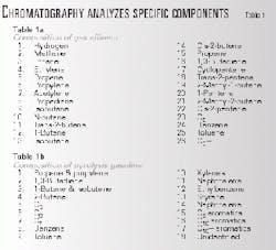
The chromatograph analyzes the 26 components shown in Table 1a. The gas density is calculated from the chromatographic composition. The relative precision of the gas density determination does not exceed 1.2%.
The final composition of the gas effluent is computed as an average composition of all analyzed contents of sampling bags.
- Pyrolysis-gasoline analysis. The sampler blends the contents of the second and third cyclones with the filtered liquid. The resulting mixture consists of water and pyrolysis gasoline, which are separated, weighed, and analyzed. Table 1b lists the 18 components and hydrocarbon groups analyzed for evaluation of cracking yields. The typical content of gasoline in process sampling is 20-150 g.
- Pyrolysis-fuel oil analysis. Technicians weigh and analyze the pyrolysis fuel oil from the first cyclone.
Simulated distillation (ASTM D 2887) determines the distillation curve of this fuel oil. The typical initial and final boiling points of pyrolysis fuel oil are 205° C. and 700° C., respectively.
The weight of the fuel oil sample is usually 5-40 g. The sampling of ethane pyrolysis accumulates no fuel oil and the sampling of LPG products pyrolysis accumulates an insignificant quantity of fuel oil.
Sampling reliability
Chemopetrol tested its new sampling device by comparing the precision of estimated product yields with carbon and hydrogen material balances.
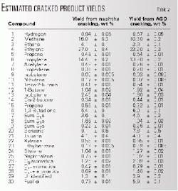
Table 2 lists estimated product yields and measuring errors from the cracking of naphtha and atmospheric gas oil in the same pyrolysis furnace based on samples collected from the new sampling equipment. The reported measuring errors are a sum of all possible inaccuracies during the sampling and chromatography analysis.
The table shows good precision of ethylene, propylene, 1,3-butadiene, and methane determinations. The heavier hydrocarbons values, such as the sum of C5-C7s, xylenes, ethylbenzene, styrene, naphthalene, and C9-C10 aromatics, were also very precise. Benzene, toluene, and hydrogen determinations had worse precisions.
The lower precisions of the benzene and toluene determinations result from the incomplete condensation of aromatics in the sampling device. Some aromatic compounds remain in the gaseous sample, and the necessary sample manipulations contribute to higher inaccuracy. The lower precision of hydrogen determination is initiated by the external unstable hydrogen calibration.
Chemopetrol checked the results of the complete yield evaluation by verifying carbon and hydrogen material balances. For this balance, Chemopetrol determined the contents of carbon and hydrogen in the feedstock and compared them to those in the complete product yield evaluation.
The accuracy of the analysis method restricts the material balance verifications; therefore, only yields of light feedstock cracking can be reliably verified. A difference in material balances of carbon and hydrogen of ±5% is usually satisfactory. More than 50 experiments using the improved sampling method had carbon and hydrogen material balance differences of less than ±2%.
Chemopetrol also compared the reliability of the improved sampling method to an older sampling method.
The original method did not allow direct and perfect separation of the pyrolysis oil, pyrolysis naphtha, and dilution water. The cracking products went through an air cooler to a cooled separation vessel, accumulating the bulk liquid products and dilution water. A subsequent series of coolers separated the residual liquid products.
Distillation separated the components of a liquid mixture; the company then weighed and analyzed each fraction. Operators collected the gas products in glass sample tubes before the chromatographic analysis.
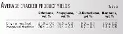
Chemopetrol performed ten pilot plant experiments with similar types of naphtha to compare the original and the improved sample methods. Table 3 presents the average yields of cracked products and the confidence limits.
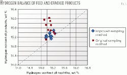
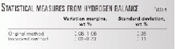
The residuals among the hydrogen balances in the raw material and pyrolysis products determined the precision criterion. Table 4 presents the variation margins and standard deviations of the identified residuals. The improved method has a significantly higher precision (Fig. 3).
The original sampling method reported higher than actual yields of ethylene and propylene lower than actual values of 1,3-butadiene and benzene. This unreliability of the original method namely results from the imperfectly separated gas and liquid hydrocarbon fractions from the analyzed reaction mixture.
References
- Leitner, W., Lemieux, E.J., Severino, F.T., and Yarze, J.C., "Commercial ethylene furnace effluent sampler and analyzer," Proc. Div. Refining, Amer. Petrol. Inst., 48, pp. 917-932, 1968.
- Wett, T., "Sample conditioner aids plant control," OGJ, Sept. 1, 1980, p. 95.
- Johnson, A., and Fisher, I.P., "Bag sampling aids FCCU studies," OGJ, Feb. 11, 1985, p. 98.
- Van der Werf, R.P., "FCC Monitoring Through Precision Testing," 39th International Petroleum Conference, Bratislava-Slovakia, Sept. 20-23, 1999.
- Germany patent 1811815, 1969.
- European patent application A1-0112407, 1982.
The authors

Thomas Herink is a research worker at Chemopetrol AS where he has worked for 3 years. He models and optimizes the steam cracking process using artificial neural networks. Herink holds an MS and is currently working on a PhD in organic technology from the Prague Institute of Chemical Technology, Czech Republic.

Peter Fulin is a senior research worker at Chemopetrol where he has worked since 1976. He researches petrochemical processes such as dicyclopentadiene or naphthalene production. Fulin holds an MS in inorganic technology from the Prague Institute of Chemical Technology and has done postgraduate studies in organic technology from the same school.

Jaromir Lederer is a senior research worker and project manager at Unipetrol. He is responsible for petrochemical research related to steam cracking and its products evaluation. Previously, he has 18 years' experience in research at technical developments at Chemopetrol. Lederer holds an MS and a PhD in chemical and fuel technology from the Prague Institute of Chemical Technology.

Zdenek Belohlav is an associate professor at the Institute of Chemical Technology, Prague. He is involved in mathematical modeling, control and optimization of chemical reactors, design of experiments, and experimental and monitoring data handling. Belohlav holds MS and PhD degrees in chemical technology from the Prague Institute of Chemical Technology.