Practical Drilling Technology
Rig area networks, remotely operated hoisting systems, more powerful drilling fluid hydraulics, and easy-to-install blowout preventer (BOP) assemblies have improved operations for several next-generation jack ups operating in the Gulf of Mexico.
Proven benefits include the ability to analyze historical and real-time drilling parameters, drill deeper wells and set larger casing strings, and hook up and test BOPs within hours.
Chiles
Since 1998, 11 new jack ups have been added to the worldwide rig fleet (Table 1).Of these, Chiles Offshore Inc.has delivered three new Explorer Class LeTourneau Super 116s: the Columbus, Magellan, and Tonala.Two more rigs, the Explorer and the Galileo, should be completed in 2002.
Built on speculation during a period of low oil prices, all three drilling units have enjoyed full employment since delivery, although most industry experts believed long-term contracts should be in place before proceeding with costly rig construction.
This philosophy is clearly evident in the recent construction cycle with most deepwater drilling rigs retaining firm operator commitments.
According to CEO Bill Chiles, however, the effects of fluctuating oil and gas prices can actually produce an environment in which long-term contracts hurt business relationships.
"If a contractor signs a multi-year contract today, with oil at $30/bbl and gas at $7/Mcf, and prices fall, the economic discord between commodity prices and contract dayrates will result in a high degree of tension." This operator-contractor strain has been publicly noted several times where major disputes between parties resulted in the collapse of the contract followed by litigation.
On the other hand, Chiles believes that a technologically enabled jack up will always find work, even during low oil and gas prices, whether or not a multiyear agreement is in place.
"Because these rigs are more efficient than existing rigs, we are staying away from the basic 'commodity' fleet," Chiles said.In turn, "we can achieve a higher dayrate." As of last month, Chiles Offshore was receiving a dayrate of about $70,000/rig.
Drilling technologies
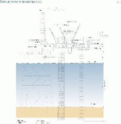
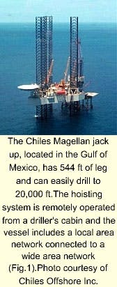
On a 3-day visit to the Chiles Magellan in the Gulf of Mexico, crewmembers showed OGJ the new systems being employed in jack up drilling operations (Figs. 1 and 2).
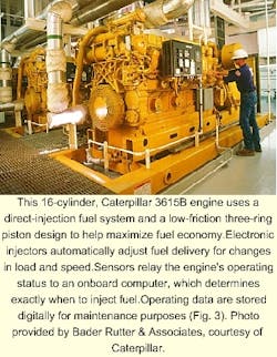
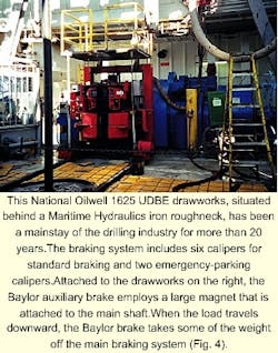
The Magellan has 544 ft of leg, three LeTourneau 50-ton pedestal cranes, four Caterpillar 3516-B diesel engines (1,855 hp each, Fig. 3), five Ross Hill 2,200-amp silicon controlled rectifier (SCR) modules, one National Oilwell 1625 UDBE drawworks with disc brakes (Fig. 4), and a National Oilwell 650-ton top drive.The 170-ft tall Loadmaster derrick is rated at 1.5 million lb static.
Additional equipment includes a National Oilwell 49.5-in.rotary table, one Maritime Hydraulics iron roughneck, and an International Tools rotating mousehole.
Drilling network
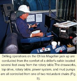
Like the advanced drillships working in the GOM, personnel operate the hoisting system from a driller's cabin set back 20 ft from the rotary table.From one of two redundant chairs, each with its own central processing unit (CPU), the driller remotely operates the drawworks, top drive, rotary table, power system, and mud pumps though National Oilwell Inc.'s Cyberbase control system (formerly Hitec, Fig. 5).
Each piece of equipment is hardwired to the driller's console through a dual-channel fiberoptic network activated by joystick commands and enabled by programmable logic circuits (PLC).This network is also used to receive information from various sensors and closed-circuit cameras placed around the rig.
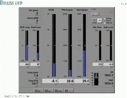
Input data include bit weight (WOB), pump pressure (PP), rotary speed (rpm), tank volumes, top-drive torque, and other parameters, configured as scalable bar graphs, charts, and digital text displayed on two consoles with customizable view screens.
The drilling console has the following views:
- Drilling: Monitors WOB, torque, PP, ROP, hook load, pump strokes, well depth, bit depth, flow rate, and pit gains (Fig. 6).
- Tripping: Monitors trip tank volume, flow rate, etc.
- Tank volumes: Monitors active tank volumes, total hole volume, total annular volume, and drillstem volume.
- Trend page-displays several selected functions with graphs and logs that can be back referenced.
- Report page: Displays and prints several customizable summary sheets.
- Well control: Calculates information to kill a well.
- Well comparison: Correlates offset well data with current well.
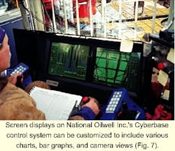
Camera views from the shale shakers, monkey board, rig floor, and BOP cellar can be "tiled" into each view as needed.While pulling the drillstring out during a bit trip, for example, the driller can easily operate the hoisting equipment, watch for increases in tank volume, and keep an eye on the derrickman as he unlatches the elevators (Fig. 7).
Trend analysis
Some of the more useful improvements include the installation of new digital sensors that resolve data one order of magnitude better than previous analog devices.For example, with digital weight indicators, rig personnel can see bit weight changes on the order of 100 lb, instead of 1,000 lb. And fluctuations in pump pressure can now be resolved to 1-5 psi instead of 100-200 psi.
"We now have the equipment to see very small changes in drilling parameters," said Donnie Sellers, rig manager for Chiles."But more importantly, these data can be tracked historically." This information in turn can be used to improve drilling efficiencies for all drilling operations.
On a recent well in the High Island Block, for example, the company man and driller used trend analysis to determine the reason for recurring fluctuations in standpipe pressure while drilling through a pay zone.
"By plotting all the variables, WOB, pump pressure, ROP, and torque, we saw a clear correlation with bit weight," said Tim Parker, day driller with Chiles."From this, we concluded that every time we increased bit weight, we reduced the fluid channel clearance near the bit, which then led to the fluctuating pump pressures."
With previous "doghouse" technologies, trend analysis on this level was not possible because many rigs recorded drilling parameters using pen recorders linked to the lower-resolution, mechanical analog devices discussed above.Thus, drillers have not historically been able to overlay current and historical data in ways needed to visualize the effects of various drilling parameters on the wellbore.
Logging-while-drilling (LWD), measurement-while-drilling (MWD), and mudlogging data will soon be at the fingertips of qualified field and office personnel as the fiberoptic network will be expanded to include these peripherals."The vision is to make all this information instantly available to the operator in the driller's cabin, and office personnel onshore, so they can make decisions with all available data," Sellers said.
Ian Russell, manager of drilling technology with Chiles and head of the company's research on telecommunication systems, has an even bolder vision for future drilling technologies: "We can give the driller tools that will help him make judgments that improve the operational process."
Thus, instead of the driller constantly reacting to wellbore conditions, he can use his experience to set up predefined constraints that improve the performance of drillfloor, bottomhole assembly, and hydraulic equipment. For example, to optimize mud motor performance while drilling a horizontal well, the system can be set up to react to differential pressure.In this way, the mud motor will not stall out and the bit will receive optimal torque levels.
Russell's work in this direction has already taken a first step as new servers with fiberoptic cables are being installed on all of Chiles's jack ups. Some of the first outside vendors to work with them include Anadrill (LWD and MWD data) and Diversified Well Logging Co.(total gas and chromatograph).
Furthermore, the rig area network is tied to Chiles's wide area network with communication links established to onshore servers via microwave or satellite transmitters.
In this way, office personnel can view live scenes from any of the rig cameras, access information from the Cyberbase control system, and even view photos of drilling cuttings taken with a 's telescopic digital camera.
Equipment innovations
Some of the more prominent innovations in the offshore drilling industry include improved well-control equipment rig-up design and more powerful drilling fluid hydraulic systems.
"Over the past 25 years, we've seen some big advances in downhole tools, but very little on the surface," say John Cormier, rig manager for Chiles."But now, improvement in BOP design, iron roughneck, mud pumps, pulsation dampeners, and solids control have really reduced the time it takes to drill a well (see box, Solids control)."
BOPs
Drilling contractors and manufacturers continue to find new ways to move non-drilling activities off of the critical path.In this regard, the time in which a BOP assembly can be rigged up, tested, and rigged down can directly impact drilling costs.
"Everything offshore is a matter of time," says Jim Downey, rig manager for Chiles."If it takes 6 hr to rig up the BOP on one rig, but 3 hr on ours, then we can save the operator close to $10,000 on this single procedure alone."
Drive pipe
The Magellan uses three BOP arrangements for the drive pipe, conductor, and surface casing strings (Fig. 8). The first arrangement, typically installed after running about 300 ft of 30-in.drive pipe, contains an overshot spool, telescoping assembly, annular preventer, diverter, no-weld adapter, and a conductor pipe tensioner.Service personnel use a pile driver to hammer the drive pipe in place.
The diverter plays an important role in directing gas away from the rig in case the well takes a kick.This is important because it is not feasible to shut in the well with a conventional ram-type BOP as the pressure would break down the soft sediments below the casing, resulting in an underground blowout.
The no-weld adapter, manufactured by Stewart & Stevenson, allows crewmembers quickly to set the diverter on the 30-in. drive pipe without a starting head or flange.
This connector, which eliminates the fire hazard of welding, seals by activating metal-to-metal engagement slips on the conductor pipe. Elastomer seals are then hydraulically pressurized to one and a half times the rated working pressure of the unit.
Conductor
The second arrangement, installed after running 1,000 ft of 16 or 20-in.conductor pipe, contains a braden head in addition to the components listed above.The braden head serves as a crossover from the larger drive pipe to the conductor and is used as a packable wellhead that seals off the annulus between these two strings.
Again, the no-weld adapter serves as a type of quick-install mechanism that expedites the nipple-up procedure. Note how the spool assembly has been telescoped upwards to make room for the braden head and swedge in Fig. 8. This versatile assembly has found great utility in jack up operations as personnel do not have to worry about measuring and cutting new pipe sections each time a new BOP assembly is run.
Surface casing
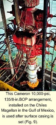
The final arrangement, rigged up after setting 3,500-5,000 ft of 16-in.surface casing, moves towards the more traditional dual-ram BOP stack as there is now competent formation underneath casing to hold a well kick (Fig. 9). As a result, this assembly excludes the diverter.
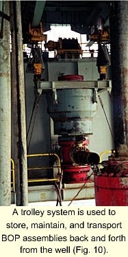
When it comes time to nipple up the BOP, the work procedure is expedited by a BOP storage and trolley system located underneath the drillfloor (Fig. 10). Thus, preassembled and pretested BOP stacks can be quickly transported over the wellhead.
To rig up the BOP, the diverter assembly is scoped upwards to give enough room to install the casing slips in the wellhead and to cut surface pipe.The two sections of the telescoping bell nipple are then pulled through the rotary and the diverter assembly is removed with the BOP trolley system.
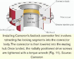
Next, the wellhead, with a premounted Cameron "FastLock," is bolted on top of the braden head (Fig. 11).When it comes time to mount the BOP stack, it then becomes a simple procedure of trolleying the BOP over and stabbing the bottom into this connector.
Crewmembers then use an impact wrench to tighten each of 18 drive screws (1,000 ft-lb each).This exerts a clamping force on the wellhead and replace the traditional nut-bolt and sledgehammer assembly.
"With this boltless system, we can now nipple up and test a BOP in 3 hr," Sellers said."Before, it could take as long as a day as we had to install each component of the stack one at a time-directly on the wellhead."
Ram removal
Another important innovation involves BOP ram removal using a horizontal ram tray instead of a vertical lift procedure. On Cameron's 10,000-psi 135/8-in TL BOP (Fig. 12), the procedure used to pull the rams includes the following steps:
- Connect the open and close ports of the BOP to the hydraulic power supply (standard hookup).
- Unload bonnet studs to ease nut removal: apply 1,500-psi opening pressure to the BOP and remove the bonnet cap nuts.
- Apply 1,500-psi closing pressure to the BOP to open the bonnets.
- Install the horizontal ram trays on the bonnet studs.
- Apply 500-psi opening pressure to clamp the tray between the body and bonnet and to move the rams to the open position.
- Install a lifting eye in the side of the rams and use a pry bar in the ram tray slots to move the ram to the side of the preventer.
- Install a lifting eye in the top of the rams and remove from the ram tray.
"We don't save much time over the prior designs, but it makes working on the BOPs much safer," Cormier said."Before, you would have to snake an air hoist down and pull the ram out vertically."
With the new design, however, "Once your (horizontal) tray is in place, you can slide it out horizontally, then attach the air hoist without worrying about the obstruction of the ram body above."
Drilling fluid hydraulics
"Perhaps the biggest change in jack up drilling operations is the substantial increase in hydraulic horsepower now available," Sellers said.Whereas 10 years ago, we could only run 20-in.casing to 1,000 ft, we can now get to 4,500 ft."
On the Magellan, more powerful mud pumps, the replacement of bladder-type dampeners with reactive dampeners, and the introduction of 57/8-in.drill pipe has helped Chiles increase its operating range in terms of casing size and well depth (see box, 57/8-in.drill pipe).
"The whole concept is to use the biggest and best equipment available so we can start out with the largest hole size possible and drill it as deep as possible," he said.For example, the rig includes three National Oilwell 14-P-220 triplex mud pumps that have a pump output capacity of 3,600 gpm each running at 105 strokes/min (9 in.liners, 2,200 hp).
Yet aside from obvious increases in "brute" mud-pump output, other technologies have come into play.
For example, the introduction of anti-synchronization mud pump technology in the mid 1990s by National Oilwell now allows the rig to place more than one pump on the well at a time without introducing vibrations and surges normally associated with dual mud-pump operations.
This leads to a smoother pumping action as only one piston places pressure on the wellbore at a time.The anti-synchronization function works through a computer program that reads stroke placement from sensors mounted to each rod.
From this information, the program alters the current load (amps) for each of the four dedicated General Electric motors through the SCR house so that pump strokes for each unit are increased or retarded accordingly.
"Basically, the concept is similar to the cruise control on a car," said Mark Sorensen, senior vice-president with National Oilwell."When the car comes up to a hill, it automatically increases the pressure on the throttle."
According to Don Dies of Schlumberger Anadril, the anti-synchronization feature, aided by new pulsation dampeners, has also improved the quality of LWD and MWD telemetric readings as there is now substantially less "rig" noise in the drilling fluid."Our LWD quality is now similar to wireline readings," he said.
Bladderless dampeners
Another hydraulic innovation includes the replacement of traditional nitrogen-charged pulsation dampeners, located on the suction and discharge sides of the mud pump, with bladderless-type reactive dampeners.
Bladder dampeners are typically precharged to 1,000 psi and are not adjusted as the pump's operating pressure increases.Thus, the nominal volume contained within the bladder is proportionally reduced as the pressure increases.This explains why noise, pulsations, and vibrations increase as the pump pressure increases.
The reactive dampeners, however, manufactured by Performance Pulsation Control Inc., Plano, Tex., use liquid compressibility to absorb pump pulsations.Because all of the drilling fluid flow passes through the unit, dampening performance remains directly proportional to the contained volume.
Thus, the greater the volume, the greater the level of dampening.On the down side, the reactive dampeners require a larger and heavier unit that takes up more space.This disadvantage, however, is offset by improved increased pump part life such as liners, rods, valves, and swabs.
New drill pipe size
As part of its program to improve hydraulic efficiencies, the Chiles Magellan uses a new drill pipe size in its Gulf of Mexico operations.Designed as a compromise between hydraulically inefficient 5 ?-in., and hard-to-handle 65/8-in.drill pipe, Grant Prideco Inc.introduced 57/8-in.drill pipe in 1999 with the delivery of 3 strings, followed by 17 more in 2000.
By reducing the annular space between the drill pipe OD and wellbore diameter, annular velocity can be increased more efficiently for any given mud-pump.For example, 57/8-in.drill pipe reduces pressure losses by 28% as compared to 5 ?-in.drill pipe.Thus, it becomes easier to maintain a clean well through a reduction in pressure losses.
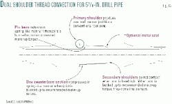
"The innovation is not the pipe size, but the tool joint design (Fig.13)," Cormier said.The 57/8-in.pipe uses a 7-in.OD, 4.25 in.ID tool joint with rounded v-form threads and a double-shouldered connection (XT 57 thread designation).
The structural makeup provides a 65% increase in working torque as compared to a similar sized API tool joint.The primary shoulder, located at the makeup point between the pin and box, serves as the sealing mechanism; while the secondary shoulder, located 7.25 in.down the tool joint, serves as a secondary torque stop.
Additionally, engineers designed the box and pin with a flush ID.While new, the tool joints have a torsional strength of 105,500 ft-lb and a tensile strength of 844,200 lb.
Cormier says service personnel recently checked 50 joints on the Magellan for wear using magnetic particle and visual inspection after drilling 29,000 ft of hole, but found only 1 joint in need of thread repair.
One drawback to the new pipe size is still weight.Whereas 51/2-in. drill pipe of comparable composition weighs 25.38 lb/ft, 57/8-in.drill pipe weighs 26.68 lb/ft, and 65/8-in.33.69 lb/ft.Thus, although it is easier to handle than 65/8-in.drill pipe, it is still somewhat difficult to rack back 57/8-in.pipe during trips without two men on the floor and a winch in the derrick.
To deal with this problem, Bill Chiles says the company will soon upgrade the jack ups to include automated pipe-handling equipment.
The human touch
Hydraulic breakthroughs that lead to cleaner hole conditions and faster penetration rates have obvious benefits in the upper and middle hole sections.
Yet it still requires human experience to maintain a stable hole to TD without problems.
For example, sloughing shales, lost circulation, and reservoir damage may result if the operator applies too much pump pressure."You can now drill pretty much as fast as you want," Sellers said."But in pay zones approaching 20,000 ft, you are limited by what the hole will let you do."
Now that drilling rig technologies have begun to fully capture the value of data, turning it into information so that the driller can knowledgeably use it, the industry can only expect more improvements in cycle time reduction and safety.


