USE OF BICENTER PDC BIT REDUCES DRILLING COST

Robert G. Casto,
Maurizio Senese Agip Petroleum Co. Inc.
Houston
The use of bicenter polycrystalline diamond compact (PDC) bit technology, dual-power-head down-hole motors, and oil-based drilling fluids helped save significant costs on a recent well drilled in the Gulf of Mexico.
Not only has underreaming been eliminated, but the overall rate of penetration has been significantly increased.
Directional control problems experienced during one phase of the well may limit use of the technique in difficult directional wells. This article discusses both the successes and the failures of this technique during the drilling of two phases of the same Gulf of Mexico well.
Grand Isle Block 102 is approximately 42 nautical miles offshore in the Gulf of
Mexico, directly south of New Orleans. The water depth in the block is 255 ft, and the prospective Pliocene pay intervals are up to 16,000-ft deep. As part of a farm-in agreement, an Exxon Co. U.S.A./Agip Petroleum Co. Inc. partnership drilled the 102-3 discovery well in 1988. Agip became operator and drilled the first delineation well, the 102-4, in January 1991. A semisubmersible rig drilled the well through an eight-slot subsea template set over the 102-3 subsea wellhead.
Agip drilled five wells and several sidetracks with the semisubmersible rig from January 1991 through June 1993. Directional plans varied from a relatively simple 25 build-and- hold well to a much more complex dual-plane, S-bend well with a maximum inclination of 61.
A platform was set over the template in February 1994, and a platform drilling rig was mobilized. The existing five wells were tied back and completed. Drilling then began on the A-1 well, which is discussed in this article.
All the wells have been characterized by mud weights as high as 16.5 ppg, problems with lost returns, and stuck pipe occurrences. Because of complex pore pressure and fracture gradi- ents, hole stability problems, and directional drilling con- siderations, seven to eight casing strings are required to reach total depth. The large number of casing strings run on these wells requires a considerable amount of under-reaming (Fig. 1) (86660 bytes).
In an attempt to reduce underreaming time and thus the overall cost of the well, it was decided to use a bicenter bit to drill and underream the two hole sections immediately below the 11 3/4-in. liner shoe. The hole sizes drilled were 10 5/8-in. x 12 1/4-in. for the 9 5/8-in. casing and 8 1/2-in. x 9 7/8-in. for the 7 3/4-in. liner.
BICENTER BIT
The advantage of using a bicenter PDC bit is that a larger hole can be drilled than the internal diameter of the previous casing string. The bicenter design consists of a pilot bit that is similar to a conventional PDC bit with a reamer section that has all the cutters moved to one side (Fig. 2) (50426 bytes).
The reamed hole size is set so that the next string of cas- ing can be run without underreaming. In Agip's Grand Isle experience, underreaming a hole to the next larger size can take more than 50% of the time required to drill the original pilot hole. Underreaming can also contribute to difficult fishing problems if the underreamer arms fail.
Bicenter bits were developed approximately 20 years ago, but have seen limited use because of several problems that have stemmed from their unusual geometry. Problems of drilling a smaller-than-expected hole, excessive cutter wear, and poor directional characteristics have been encountered in early designs.1
A unique feature of bicenter bit technology is that the design is dominated by three diameters: the pilot bit diameter, the drill hole diameter, and the pass through diameter (Fig. 3) (58862 bytes). Because of the bicenter bit geometry, the bit is free to move to one side of the hole during the trip through the casing. This capability is what allows the bit to pass through a hole that is smaller than what it drills (Fig. 4) (65635 bytes).
During drilling operations, the pilot bit is centered in the hole, and the offset blades are forced to ream the hole to the larger size (Fig. 5) (65892 bytes). Since the reaming cutters are all on one side of the hole, the opposite side cutters of the pilot bit are very highly loaded. This load has resulted in the bicenter bit being an unstable design.
The bicenter bit is impossible to stabilize fully because the largest stabilizer size that cart be used is the pass-through diameter, not the hole diameter. In addition, no stabilizer can be placed immediately above the bit because of geometrical con- siderations when the bit is run through the casing. This factor also limits the diameter of the downhole motor that can be run behind the bicenter bit. Recent design advances in bicenter bit technology have reduced the inherent instability of the bit design)
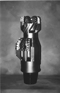
Fig. 6 is a photograph of the bicenter bit used in the upper hole section of the A-1 well. Bicenter bits typically cost approximately seven times the amount of a typical insert bit of the same size.
DOWNHOLE MOTOR
The A-1 well's directional plan called for holding an inclination of 37 from the 11 3/4-in. shoe to total depth. A steerable downhole motor was required to maintain directional control. The geometry of the 10 5/8-in. 3 12 1/4-in. bicenter bit required that the bottom hole assembly be no larger than 7 7/8 in. within 30 ft of the bit. A 6 3/4-in., 7/8-lobe downhole motor was therefore selected.
Other operators' experiences with this bit had indicated that a standard 6 3/4-in. motor would not provide sufficient torque to produce an acceptable rate of penetration. In 1992, advances in downhole motor technology resulted in the development of a dual-power-head motor, which essentially doubles the motor's torque output.2 The dual-power-head motor basically consists of two motors connected in series (Fig. 7) (52715 bytes).
After the setting of the 9 5/8-in. casing, the geometry of the 8 1/2-in. X 9 7/8-in. bicenter bit required that a motor no larger that 6 1/8-in. in diameter be run. The next size down in the dual-power-head motors available was a 4 3/4-in., 7/8-lobe motor.
The dual-power-head motors are approximately 50% more expensive to run than conventional single-stage downhole motors.
BOTTOM HOLE ASSEMBLY
The bottom hole assemblies were limited both by the restrictions from the bicenter bit's geometry and by the fact that the hole was being underreamed at the same time it was being drilled.
The use of full-gauge stabilizers for the underreamed hole diameter was not possible. Table 1 (22072 bytes) lists the dimensional considerations that governed the bottom hole assembly design for each of the two hole sections in the A-1 well.
The limitations on tool diameter made it very difficult to achieve a stable bottom hole assembly.
Well A-1
After the 11 3/4-in. liner was set at a depth of 11,875-ft measured depth (MD), 11,528-ft true vertical depth (TVD), a 16.4- ppg leak-off test was obtained with water-based mud. The water- based mud was then displaced with an invert-emulsion, mineral- oil-based mud.
The next casing planned for the well was 9 5/8 in. Normal operations would have been to drill a 10 5/8-in. hole and then underream it to 12 1/4 in. A decision was made to purchase a PDC- cutter bicenter bit that would drill a 12 1/4 in. hole below the 11 3/4-in. liner in one pass.
The maximum diameter bottom hole assembly allowed with this bit is 7 7/8 in. (within 30 ft of the bit). A 6 3/4-in. dual- power-head, bent-sub motor was used to provide the high amount of torque required and still be of a small enough diameter to work with the bicenter bit.
12 1/4-IN. HOLE
A single bicenter bit drilled the entire interval from 12,160-ft MD to 15,001-ft MD (14,075 ft TVD) in mud weights ranging from 14.8 to 15.7 ppg at total depth. The dual-power- head motor made the entire run also.
The drilled formations consisted of 70-90% shale, 10-20% siltstone, and 0-10% sandstone.
Fig. 8 (54780 bytes) shows the overall rate of penetration of the bicenter bit versus the pilot bit runs of two offset wells that were drilled with similar directional plans, the same oil-based mud, and conventional insert bits. The penetration rates plotted include time for connections but do not include trip time.
At first glance, the penetration rates appear similar. This result would be impressive in itself, because the bicenter bit both drilled the pilot hole and underreamed it in the same pass. If the effect of bit trips is included, however, the bicenter bit performance is even more impressive.
The 2,841-ft long interval was drilled in a total of 4 1/2 days for an overall average penetration rate of 26 if/hr. The two offset wells were drilled at an average of only 15 if/hr. The overall penetration rate for the bicenter bit was approximately 70% faster than that for conventional bits drilling a hole of the pilot bit size.
Instantaneous penetration rates were much greater than the overall average noted above. Only 49 hr of on-bottom rotating time were used to drill the 2,841 ft, for an average penetration rate of 58 if/hr. In addition, a large portion of this interval was drilled in a sliding mode with an average inclination of 34. Sliding rates of more than 100 ft/hr were achieved.
The bit carne out in essentially new condition, and a caliper log run indicated the hole was 12 1/4-in. gauge all the way to within 100 ff of bottom (where the pore pressure began increasing). The bit run for the 12 1/4-in. hole was an overwhelming success. Not only was the overall rate of penetration increased by 70% (thus saving 3 1/2 days of drilling time), a minimum of 4 days of underreaming time was eliminated. The cost savings were approximately $400,000.
The main concern prior to the bicenter bit run was the stability of the bottom hole assembly and whether the directional drillers would be able to control the well path. Fig. 9 (58252 bytes) illustrates the dogleg severity of all the surveys on the A-1 well and two similar offsets. The bicenter bit created some problems for the directional driller and increased the amount of sliding required, but dogleg severity was controlled to an acceptable 3/100 ft.
9 7/8-IN. HOLE
After the 9%-in. casing was set at 15,000-ft MD (14,075-ft TVD), an 8 1/2-in. x 9 7/8-in. bicenter bit was selected for the next section of hole.
The only bicenter bit available had a 6 1/8-in. pilot bit and could accept a maximum of a 6 1/8-in. motor. The only avail- able dual-power-head motor that would work with this bit was 4 3/4-in. in outside diameter.
The bit manufacturer currently has a design for this bit with a 6 3/4-in. pilot bit that would have allowed the use of the sturdier and more powerful 6 3/4-in. motor.
The bit was run on the 4 3/4-in., dual-power-head motor and drilled from 15,010 to 16,838 ft MD, where the mud motor's stator failed after 68 hr of drilling. The overall rate of penetration was 22 ft/hr, which is roughly equivalent to offset performance with conventional bits.
Directional control of the well became very difficult in this section (Fig. 9) (58252 bytes). Dogleg severity averaged 4/100 ft, with one survey indicating 7/100 ft. These surveys were in a "hold inclination" section of the well. Approximately 60% of the drilling time was in the sliding mode, as opposed to rotating.
After the motor was replaced, the bicenter bit was run again. Another 100 ft were drilled, but the entire interval had to be drilled in the sliding mode with average penetration rates of only 5 if/hr. Concerns about the possibility of sticking the pipe and continued directional problems prompted a decision to pull the bicenter bit.
The hole was finished with a conventional PDC bit at overall penetration rates of approximately 10 if/hr. The upper part of the hole (the part drilled with the bicenter bit) did not have to be under-reamed, which resulted in a savings of approximately $50,000.
HYDRAULICS
Hydraulics and hole cleaning were a concern, especially in the 12 1/4-in. hole section. The bicenter bit was equipped with seven nozzles, each with a 15/32-in. diameter.
The initial hydraulics calculations assumed that there would be 800 psi of loss across the mud motor when it was on bottom and drilling. The bit manufacturer requested a minimum bit pressure drop of 200 psi. The safe operating pressure limit for the mud pumps was 3,000 psi. The initial calculations indicated that at 15,000-ft MD, a flow rate of 470 gpm would be achievable.
The actual pump rates used on the well varied from 551 gpm initially to a low of 393 gpm at total depth. The mud properties were such that no fill or hole cleaning problems were noted. The bit was operated at 2,000-13,000 lb weight on bit and rotated at 400-550 rpm.
MUD PROGRAM
The mud system on all three of the wells compared in this article was an invert-emulsion, mineral-oil-based system. The mud system was maintained with 4-6 lb/bbl of excess lime and a water- phase salinity of approximately 300,000 ppm.
The pump rates achieved in the 12 1/4-in. hole translate into annular velocities (outside the drill pipe) of 108-77 fpm. The mud properties were adjusted to maintain adequate hole cleaning in this 37-inclination well. The volume of drill cut- tings produced was carefully monitored and compared to the theoretical cuttings volume to ensure that the hole was being properly cleaned and that excessive washouts were not developing.
Typical mud properties for the 12 1/4-in. hole are summa- rized in Table 2 (50426 bytes).
RESULTS
- The use of bicenter bits can substantially reduce drilling costs by eliminating the time required for under-reaming.
- The inherent geometry of the bicenter bit limits the diam- eter of downhole motors and stabilizers that can be run in the bottom hole assembly. These limitations can make the well difficult to control directionally.
- The use of adjustable-blade stabilizers could greatly increase the usability of a bicenter bit in directionally drilled wells. The gauge change required for a hall-gauge stabilizer is 1.625 in. for the 10 5/8-in. x by 12 1/4-in. bit and 1.375 in. for the 8 1/2-in. x 9 7/8-in. bit.
ACKNOWLEDGMENT
The authors thank Agip Petroleum Co. Inc. for permission to publish this article. In addition, the following personnel contributed data, graphics, and assistance: Onofrio Ragusa and Paolo Macculi, Agip rig supervisors during the bicenter bit run; Eric Johnson and Coy M. Fielder of Diamond Products International Inc.; Carl Hight of Baroid Drilling Fluids Inc.; and Jerry Keen and Stewart Yee of Sperry Sun Drilling Services.