Coating, CP failures behind corrosion problems on African fuel oil line
Laboratory analyses of a section of 8-in. pipe in heavy-fuel-oil service revealed failure from damaged coating and thermal insulation and from inefficient cathodic protection (CP).
The carbon steel pipeline carries heavy fuel oil from an oil refinery to large storage tanks before it is consumed by several boilers at a nearby electrical power station. The 34-km line had failed frequently in the previous 20 years of continuous service.
Laboratory investigation conducted on the pipe section includes visual, microscope, metallographic examinations as well as chemical and microbiological analyses of soil and clay from the area around the failed pipe. The results revealed that the pipe has suffered from severe general and pitting corrosion attack within a small, restricted area.
The main causes of corrosion were attributed to the moderate temperature of pipeline surface and the presence of a considerable quantity of chloride ions along with a high count of sulfate-reducing bacteria (SRB) within the soil and clay in contact with the failed pipe.
Dual protection
Among the many threats to pipeline integrity are third-party damage, geological activity, and corrosion.1-3 One of most common threats, external corrosion, has been recognized for many years as the main deterioration mechanism that can reduce the structural integrity of buried pipelines.1
Generally, pipelines are protected from such corrosion attack by a dual system of protective coating and cathodic protection (CP). Each of these methods when properly operated can provide the protection necessary to prevent leaks and ruptures in the pipeline.
In some cases, however, coating can fail in such ways as to shield a corrosion cell on the pipe surface under degraded coating. When that happens, adequate CP current should be available at the site of the breakdown for corrosion prevention.
Failure of the entire protective system (coating and cathodic protection) can lead to pipeline corrosion, leaks, and ruptures.1 2
The most recent corrosion and leakage on the 34 km heavy-fuel-oil line was reported in July 1999, when several inspectors detected oil leaking from the pipeline in an area near the refinery.
As general practice, the inspector had replaced the severely corroded and pitted pipe section with a new pipe section, while the corroded section was subjected to detailed metallurgical investigation to ascertain the main cause of pipe corrosion and leakage.
The pipeline segment examined was 8.518 in. OD, 7.04 mm (0.277 in.) WT, 5L X-54 weighing 24.70 lb/ft. It was being operated under 60 kg/sq cm (approximately 850 psi) at a temperature that varied from 60
The pipeline was installed in 1974, put in service in 1975, and continuously used to carry warm heavy fuel oil from an oil refinery to the oil tanks.
In order to keep the oil warm, the line was insulated with polyurethane thermal insulator and, to avoid external corrosion, was coated with asphalt-containing material.
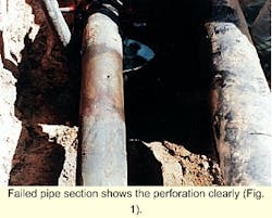
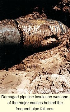
Unfortunately, damaged insulation and coating allowed frequent corrosion and pipeline leaks between 1975 and 1993. Figs. 1 and 2 show typical examples of the failed coating, corrosion damage, "pipe perforation," and damaged insulation.
Therefore, it was decided in 1993 to install cathodic protection along with protective coating.
Inexplicably, however, the CP technique failed to prevent the pipeline from corroding and leaking. Several leaks were reported after installation of the CP system, the latest being July 1999.
Investigation
The replaced pipe section was 50 cm long and was received from an oil distribution company in order to determine the cause and severity of the corrosion attack.
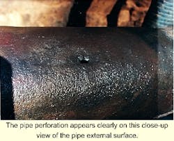
The examined pipe section showed severe, uniform, and mainly corrosion attack. One pit (leaking area) was found at the thinnest area (0.2 mm) on the pipe surface (Fig. 3). Therefore, it was decided to perform thickness measurements on the entire pipe as well as around the severely corroded area.
These measurements revealed that the pipe had suffered from severe uniform corrosion or marked reduction in pipe wall thickness (Fig. 4).
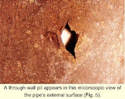
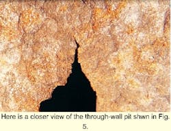
The results of microscopic examination carried out on the corroded pipe section showed that the pipe had suffered from severe thinning (thickness reduction) and pitting corrosion (pipe perforation) at the thinnest part of the pipe section (Fig. 5).
The examination also revealed that the pit-growth mechanism was by initiation of several cracks from pit tips and propagation of these cracks through the thinnest cross-section (Fig. 5). The crack propagation was assisted by the high internal pressure of flowing crude in the pipeline (Fig. 6).
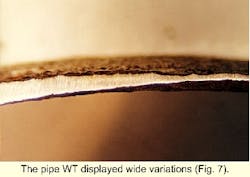
Fig. 7 shows a general view for the pipe wall thickness where a wide variation in the wall thickness is visible. This indicates that the corrosion process was localized (that is, anodic site surrounded by the cathodic area). The anodic site is the uncoated area (bare steel), surrounded by large cathodic area that is coated and cathodically protected.
Several specimens were prepared for detailed metallographic examination to characterize or identify the type of pipe microstructure. The results showed that the pipe microstructure consists of ferrite and pearlite bands, a typical microstructure of Grade X-52 carbon steel pipe made in accordance with API-5L specification.
One sample from the pipe section was chemically analyzed; the results confirm that the pipe is made of carbon steel and meets the grade requirements. The amount of aluminum was found to be negligible, however.
This is typical chemical analysis of pipelines made before late 1970s. Addition of this element is necessary to clean up the steel of such other detrimental elements as oxygen and nitrogen.
In contrast, the absence of aluminum will result in aging of steel and therefore reduction of some of the mechanical properties such as toughness and strength in transversal direction.
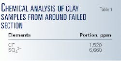
Samples of clay collected from the area around the failed pipe were subjected to chemical analysis to detect the level of dangerous ions (such as chloride ion, sulfate, and other elements) expected to have a role in pipe corrosion. The results showed that the clay consists of considerable chloride and sulfate ions (Table 1).
Chloride ions are known to have a marked effect on pipeline corrosion, while sulfate ions themselves are not dangerous and actually retard the corrosion process of steels.
When some types of bacteria, however, such as sulfate-reducing bacteria (SRB) are present in the soil (or clay), the corrosion process of steel will be markedly increased by the sulfide ions (HS-) or sulfur ions (S- -).
These ions are produced by the reduction of sulfate ions by the presence of SRB in the surrounding soil. The sulfide or elemental sulfur is very dangerous and can cause severe corrosion to carbon steel.
Several soil and corrosion products samples were subjected to microbiological analysis to detect the presence of some types of bacteria, namely iron bacteria (IB) and SRB, known to have an important role in corrosion in carbon steel.
The results of tests conducted in accordance with API standard methods confirmed the presence of high count of SRB in all tested clay and corrosion product samples (Table 2). This is expected in the light of soil chemical analysis results.
This type of bacteria (anaerobic bacteria) is a major contributor to pipe corrosion and failure.
Factors
The results of both on-site and laboratory investigations revealed that the pipe had suffered from severe localized corrosion resulting from a combination of degradation of insulation, coating failure, inadequate or inefficient cathodic protection (under failed coating), and corrosion attack.
The second and third items can be considered as one factor because they depend on each other. The last is effective when the first three are not working or inefficient.
The effect of each factor on the corrosion process is as follows:
Failed insulation and coating. Polyurethane foam on the pipe when exposed to water at the fuel oil's pipeline temperature (70-80On-site investigation showed that the pipe-coating failure (cracked and easily removed by bare hands) could be attributed to the fact that asphalt-based coatings are subject to oxidation and loss of lower molecular weight components through water dissolution and biodegradation (presence of bacteria) over time.
These processes result in a permeable embrittled coating, often in the field excavation found separated from the pipe surface by a small gap.1 Water penetration through this coating leads to exposure of the underlying steel to the surrounding environment which in the current case consists of clay saturated with water, chloride ions, and micro-organisms (SRB).
Two other factors can cause coating failure or disbondment:
A prerequisite for corrosion to occur under disbonded tape coating is that cathodic-protection potentials do not reach the pipe surface.
This can be explained as follows: Failure of the disbonded tape (asphalt) to lose its electrical insulating ability blocks the direct access of cathodic protection current to the underlying steel through the displaced tape coating.1
Corrosion mechanism
Where circumstances defeat the pipe protection normally provided by coating and cathodic-protection systems, external corrosion can be a major integrity threat for buried pipeline systems.
Corrosion of pipeline steel occurs by a series of electrochemical reactions, which can be simplified as follows:
Fe > Fe2+ + 2e-
(anodic reaction)
2H+ + 2e- > 2H-
(cathodic reaction in presence of SRB)
Based on the results of the investigation carried out on the received samples (steel pipe and clay soil), the suggested corrosion mechanism derives from the formation of a galvanic coupling between microbially produced iron sulfides and the steel surface.
The electrical conductivity of the iron sulfide (FeS) can have a pronounced influence on the current density required to maintain adequate cathodic-protection potentials on the steel surface. The cathodic system in effect tries to protect the FeS in contact with the pipe.
Because iron sulfide is present as a very finely divided black solid with very high surface area, extraordinarily high current densities are needed to sustain the protective potentials. Therefore, the exposed steel surface will not be cathodically protected and will suffer from severe localized corrosion as in this case.
This mechanism is the most common, particular for wrapped pipelines in wet high clay soils. The corrosion process will be markedly assisted by the chloride ions present with considerable quantity in the soil or clay.1
Preventive measures
The inevitability of degradation with time of insulation of thermally insulated pipelines, of water absorption by degraded insulation, and of the inability of CP system to protect the pipeline's surface from most of corrosion caused by water absorbed by the insulation was recognized.
Such corrosion can be delayed, however, by a proper choice of coating and enforcement of quality control during field installation and repairs. Any such barrier coating and wraps nevertheless will eventually break down under the effect of heat (hot fuel oil), water, or heat and water together.
At that time an adequate CP current should be available at the site of the coating breakdown for corrosion prevention.
One suggested technique is to incorporate anodes within the insulation as a way of ensuring delivery of CP current to a corroding pipeline surface.
Also, many coating systems have become available in the last 10 years to provide a considerable barrier to intrusion of ground water to the pipeline surface. High-solid epoxies, fusion-bonded epoxy, cloth-coatings, and tape systems have excellent resistance to heat and water.
The oil distribution company responsible on the failed section of pipeline has taken the following remedial actions,
- The failed pipeline section was replaced with a new pipe section taken from one of many surplus pipelines made from same steel grade, API 5L X-52.
- The replaced pipeline section was carefully welded with qualified welding procedure specifications, including selection of the correct welding electrodes.
- The replaced pipeline section and 0.5 m from both sides were coated with asphalt-based coating.
- The replaced section was thermally insulated with polyurethane foam. The maintenance engineers made sure that this insulation is fully homogenous with the old reliable thermal insulation.
- The new insulation afterward was covered with asphalt-based tape.
- The replaced section of pipeline was buried with dry sand containing no chlorides. This was to ensure good working condition for the applied cathodic protection.
The company is also considering a new inspection technique, an attenuation method called C-SCAN. This method can offer several services such as localization of buried pipes (depth), overall checking of the general coating condition, and positioning of various coating defects.
This technique can locate the severely corroded areas, damaged insulation, and coating. Based on the obtained information, the preventive maintenance program will be scheduled to combat any future failures.
References
- Jack, T. R., Wilmott, M. J., Sutherby, R. L., and Worthingham, R.G., Corrosion95, NACE, 1995.
- Fitzegerald, G.H., Materials Performance, October 1989, p. 17.
- ASM Handbook, Failure Analysis and Prevention, Vol. 1, 8th Ed., (Materials Park, Ohio: ASM International, 1986).
The authors
F. Elshawesh is head of the corrosion division of the Petroleum Research Center, Tripoli. He has 15 years' experience in failure analysis for oil, gas, and industrial sectors. He holds a BSc (1985) from Alfatah University, Tripoli, and PhD (1992) from Leeds University, UK.
A. El Houd is a researcher at the Petroleum Research Center. He holds a BSc (1990) from Alfatah University and an MSc (1998) from Manchester (UMIST), UK.
M. Elshushan is senior corrosion engineer with the Brega Petroleum Marketing Co., Tripoli. He holds a BSc (1981) in chemical engineering from Alfatah University.

