Design, equipment changes make possible high C3 recovery
Recent advances in the process design of cryogenic gas-processing plants and in their equipment have led to development of a high NGL-recovery process flowsheet that can cost-effectively yield propane recoveries of up to 99%.
The flowsheet was chosen for a major European NGL-recovery project; and its principles are applicable to any NGL-recovery project. Their use gives higher recovery rates with little or no increase in power consumption and thus improves overall economics.
Economic justification
Recent years have seen intense activity in gas processing projects around the world, driven mainly by gas utilization for power generation. This trend will continue in response to environmental pressures.
Removal of a portion of NGL in the gas is normally required to meet hydrocarbon dewpoint specification both for pipeline transportation and to prevent liquid dropout prior to gas turbines.
For large-scale projects, economics often justify high NGL recovery to yield liquid products for petrochemical feedstock or for motor-gasoline blending stock in the case of natural gasoline. The optimum NGL recovery is highly site and project specific, but the principles used to identify the optimum recovery are similar on every project.
In contrast to the traditional North American ethane recovery plant, many NGL extraction plants now being built or planned have no ready outlet for ethane. Development of marginal fields with relatively high nitrogen and carbon dioxide levels often means that ethane must remain in the sales gas to meet heating value specifications.
Many plants are therefore designed to recover a large proportion of propane from the natural gas feed but little or no ethane.
The UK has been a major area for gas processing projects in the 1990s, and many new gas fields have been developed, including those in the Central North Sea. While these fields are less rich in NGL than those in the Northern North Sea, some propane removal is needed to meet National Transmission System (NTS) specifications.
Increased propane recovery, greater than the minimum for the NTS, can be justified. In a recent UK project, the optimal flowsheet and NGL recovery were identified from a series of process options.
The lessons learned from this exercise were further developed and applied to a subsequent project in the Norwegian sector where very high propane recoveries could be justified.
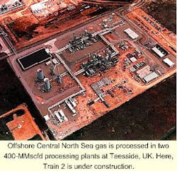
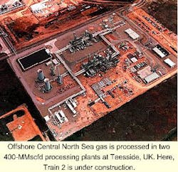
Teesside gas plants
The Central Area Transmission System (CATS) was brought on stream in 1993 to transport gas from the Central North Sea to Teesside in northeast England (OGJ, June 7, 1993, p. 37). Initial gas production of up to 400 MMscfd was for use in an 1,875-Mw combined heat and power station, operated by Enron at Teesside.
The CATS gas is transported in dense phase to avoid any liquid formation in the subsea pipeline, with a landfall pressure of up to 125 bara (more than 1,800 psia). Upon moving ashore, the gas is routed to a receiving terminal, operated by BP Amoco, and then to Enron's gas processing facilities.
The original gas processing plant was built to condition the gas prior to utilization in the Teesside power station, to extract NGL to avoid liquid dropout prior to the power station, and to fractionate the NGL into propane, butane, and natural gasoline.1
This gas processing plant was completed in 1993 and the establishment of the associated infrastructure for gas handling, processing, and gas and liquids transportation at Teesside provided stimulus for further development of the Central Area.
In 1996, a second gas processing plant was brought on stream by Enron on the same site. This plant processes a further 400 MMscfd of CATS gas for export to the NTS and local industrial customers.
The first Enron gas processing plant (Train 1) utilizes Joule-Thomson expansion between the high-pressure feed gas and power-station supply pressure (38 bara) to generate refrigeration and thus extract NGL.
The simplicity of the process and the relatively few equipment items ensure high reliability and high plant availability, which are key requirements in maximizing plant on-line time and minimizing power station fuel costs.1-3
The second gas processing plant (Train 2) was required to export gas at up to 73 bara into the NTS which demands more stringent export specifications than Train 1 in terms of calorific value, Wobbe Number, and maximum contaminant levels.
As a result of the sales contracts, NGL often has greater value extracted as liquid than if left in the sales gas.
The plant design therefore had to permit maximum rejection of NGL components into sales gas (subject to Wobbe Number constraints) or allow high recovery of NGL so that product revenues can be maximized based on the relative price of sales gas and liquid products.4
Design
As part of the development of the Train 2 gas processing plant, conceptual design work and techno-economic analyses determined the optimal propane recovery that would maximize return on investment for the project. Meeting sales-gas specifications for gas heating value and Wobbe Number required a propane recovery of only about 25%.
This could have been achieved by a Joule-Thomson process without need for any sales-gas compression in a simple, low-capital plant, albeit the plant would have lacked flexibility to feed-gas composition changes.
The main drawback of such low NGL recovery was that a better return on investment was achievable with a more-efficient process of higher capital cost but also with much higher NGL recovery.
Increased NGL recovery required the use of a turboexpander in lieu of a Joule-Thomson valve. A typical flowsheet for a simple turboexpander plant is shown in Fig. 1. The high feed-gas pressure of more than 100 bara meant that a significant quantity of work could be generated by the turboexpander for product gas compression.
A propane recovery approaching 80% was possible with the turboexpander performing all sales-gas compression. Obtaining more than 80% propane recovery required operating temperatures of less than -70° C. This would need a minimum operating pressure of less than 40 bara, and externally driven sales-gas compression would then be needed in addition to that provided by work-expansion.
Propane recovery could have been increased to slightly more than 80% without standalone sales-gas compression by installation of additional heat-exchange area. This was not deemed cost-effective, as the capital cost of additional heat-exchanger surface area compared to the additional NGL produced did not pay out with sufficient return.
A more complex flowsheet, with more equipment items, could also have increased NGL recovery but would have marked a major departure from the ethos of process simplicity and commonality with Train 1.
Although very high NGL recovery could be obtained with standalone sales-gas compression, the marginal increase in NGL revenues gave a negative return on investment, due mainly to the very high compressor capital and operating costs.
It was clear, that for this project and the NGL values used for project economics, the best process options would be those with all sales-gas compression being performed by feed-gas turboexpansion. A similar conclusion was reached for another large North Sea gas processing project.5
Turboexpanders in series
A number of alternative turboexpander-based process flowsheets were developed and evaluated as part of conceptual design and process optimization. These studies identified that two distinct stages of work expansion would result in a less-expensive plant than by following conventional practice and using only one stage of work expansion. NGL recoveries were similar for the two options at around 80%.
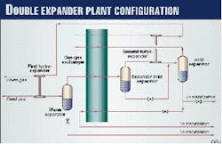
Fig. 2 shows the use of two expanders. Dry feed gas is reduced in pressure via the first expander, causing condensation of heavier hydrocarbons. The resultant two-phase mixture is separated in the warm separator.
Vapor from this separator is cooled and condensed in the gas-gas exchanger, and the mixture then passes to the cold expander inlet separator. The vapor is further reduced in pressure via the second expander, giving rise to further condensation, and the vapor and liquid formed are separated in the cold separator along with the cold liquid from the expander inlet separator.
The vapor from the cold separator is reheated in the gas-gas exchanger and compressed in the turboexpander brake ends. The liquid from the cold separator is split before being fed to the de-ethanizer so that a part of the liquids can be reheated to improve energy efficiency and NGL recovery. A side-reboiler on the de-ethanizer would be equally effective.
The use of two turboexpanders in series enabled the design pressure of the gas-gas exchanger to be reduced enough for a plate-fin heat exchanger to be used on this service. A single stage of work expansion would have meant the gas-gas exchanger being located at the front end of the plant, and the design pressure of almost 150 barg would have required a shell-and-tube exchanger.
Because aluminum plate-fin exchangers operate with small temperature differences, they can use the refrigeration generated by the work-expansion of the natural gas very effectively. They also enable multiple process streams to be energy integrated in one exchanger that also makes good use of the available refrigeration.
They have low cost per unit area, so that a large surface area can be justified much more easily than it could be with a shell-and-tube exchanger.
The so-called "double-expander" flowsheet has the advantage that even with one turboexpander off-line, NGL recovery can remain high. Even more important, for a single turboexpander to give about 80% propane recovery, a large quantity of unstable liquid would be formed in the expander exhaust stream due to the relatively high pressure ratio across the machine.
There is only limited experience of expanders with high liquid formation (more than 40 wt %) in the exhaust, and it is known that excessive liquids formation in the machine can cause severe vibration and reliability problems.6
The double-expander plant was therefore considered optimal, compared to a single expander plant, from consideration of overall costs, reliability, flexibility to changes in feed conditions, and ease of operation.
Further process optimization work considered the de-ethanizer's operating pressure and the degree of reheat of cold-separator liquid in the gas-gas exchanger in parallel with the optimization and selection of the de-ethanizer's overhead compressors.
The Train 2 gas-processing plant project proceeded to detailed engineering, procurement, and construction with the double-expander flowsheet and a propane recovery of nearly 80%. This recovery gave the maximum rate of return.
Higher propane recovery would have required expensive standalone sales-gas compression or greater process complexity or both. Neither could be justified.
Many important lessons were learned from this project that would be of value for future NGL recovery projects.
Kårsto plant
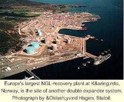
In June 1996, the Norwegian parliament approved the landing of the gas pipeline from the Åsgard field at the Kårsto gas plant on the west coast of Norway. This action initiated expansion of the existing Kårsto facilities to process the gas and recover NGL.
The existing Kårsto gas processing facilities handle 775 MMscfd of rich gas in two turboexpander plants with an additional 100 MMscfd bypassed around the plants. The gas plant is Europe's largest NGL and condensate processing complex. While it would have been possible to add a similar process train for the Åsgard gas, it was identified that increased NGL recovery would be favorable due to the margin between NGL and sales gas and the potential to produce more, if slightly leaner, sales gas.
The existing infrastructure at Kårsto for NGL production made it a more attractive site than Kollsnes, along the coast, which would have required a new NGL plant. To handle the additional gas, however, a new pipeline, Europipe II, is required to run from Kårsto to Dornum, Germany.
Double-expander flowsheet
An important aspect of overall process optimization of the new gas processing facilities was to identify the optimal NGL-extraction process based on energy efficiency, reliability, and life cycle cost.
Norwegian legislation is such that energy efficiency commands a higher premium in Norway than in many other parts of the world.
A base case NGL-extraction process had been identified by Statoil as part of the plan for development and operation of the new facilities. This base case was relatively conventional and similar to the existing Kårsto gas plant flowsheet in having pressure letdown through a Joule-Thomson valve and then through a turboexpander.
The propane recovery of this flowsheet, about 78%, was anticipated to be less than the existing plants. This base case produced export gas at about 42 bara for subsequent compression to Europipe II maximum operating pressure of 190 bara.
It was clear that the large export gas flow and the high pressure ratio for sales-gas compression would inevitably mean that machinery size and cost would have a major impact on process optimization and project cost.
The base-case flowsheet with Joule-Thomson letdown of dense-phase gas followed by a turboexpander had been evaluated during the conceptual design of the Teesside facilities. It had been rejected on that project in favor of the double-expander flowsheet, based on life-cycle costs, primarily because of its lower NGL recovery.
As a preliminary assessment, the performance of the two flowsheets was now compared.
The double-expander process actually gave slightly lower overall NGL recovery, but the fact that export gas could be produced at around 70 bara by the brake ends of the expanders meant that standalone-compression power requirements were reduced significantly compared to the base-case design.
The double-expander flowsheet developed for the Teesside facilities thus became a starting point for conceptual design studies for the Åsgard development.
Options
There was a key difference between the process optimization work for the Enron Teesside facilities and the Åsgard project: For Teesside, standalone compression could be sensibly avoided; the need to export sales gas at very high pressure to the Europipe II pipeline system meant that standalone compression was mandatory for Åsgard.
Consequently, the Åsgard process optimization presented more choices in the selection of operating parameters and process flowsheet. Furthermore, it was realized that the project size and machinery requirements would justify a much higher percentage NGL recovery than Teesside.
Potentially, NGL recovery up to about the minimum sales-gas heating value specification could be justified. This was equivalent to about 95% propane recovery.
A series of evaluations of alternative NGL extraction schemes was initiated. The clear objective was to maximize NGL recovery to increase product revenues while minimizing sales-gas compression power to avoid excessive capital cost.
Such objectives are traditionally met by consideration of overall plant thermodynamic efficiency.
For a natural gas processing plant which uses multistream plate-fin exchangers, very small temperature differences are achievable at relatively low cost. The temperature-enthalpy diagram for the heating and cooling streams of the process shows whether the process is operating at reasonably small temperature differences; if not, further heat exchange is normally justified.
The overall improvement in process thermodynamic efficiency by "closing-up" process temperature driving forces can substantially reduce process power consumption and sales-gas compressor cost. Avoiding excessive heat-exchanger cost normally means employing plate-fin exchangers.
Process optimization then essentially becomes an exercise in determining and analyzing temperature-enthalpy diagrams and making process improvements based upon what is shown by the diagrams.
Traditionally, natural gas processing plants have operated at relatively low thermodynamic efficiency, and there is considerable scope for improving process flowsheets to improve NGL recovery or reduce compression requirements or often both.
Efficiency improvements
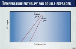
The double-expander process temperature-enthalpy diagram (Fig. 3) is characterized by a wide temperature difference between the condensing feed stream and the returning methane-rich gas at the cold end of the gas-gas exchanger.
This wide temperature difference represents thermodynamic inefficiency and a loss of potential to improve the process. It is inherent in all turboexpander plants to a greater or lesser extent and the double-expander plant is in itself better in this regard than other turboexpander-based flowsheets.
The large temperature difference means that the returning lean gas is available at a cold enough temperature potentially to reduce the feed temperature further and thus increase NGL recovery, if used in a different fashion.
The process options studied to improve NGL recovery were developed from the Teesside evaluations and earlier patented work. One such patent gives a relatively simple yet radical process flowsheet for NGL recovery.7
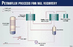
This flowsheet uses a reflux exchanger (or dephlegmator). A plant using this process flowsheet proved that high propane recovery could be achieved with much lower power consumption than competing processes.8
As shown in Fig. 4, the vapor stream leaving the separator is partially condensed in the reflux exchanger, thus effecting a separation. The resultant liquid condensate from the bottom of the reflux exchanger is combined with the liquid resulting from partial condensation and routed to the stabilizer.
The returning cold vapor and an external refrigeration system provide refrigeration for the process.
The reflux exchanger essentially operates similar to the upper part of a distillation column, but temperature differences are small and the composition differences between vapor and liquid are small. Therefore the extraction of NGL is effected close to equilibrium conditions with high thermodynamic efficiency; this is crucial to minimizing process power requirements.
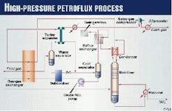
A similar process flowsheet, using the reflux exchanger principle, is shown in Fig. 5. This patented process was developed for feed-gas pressures well in excess of those at which separation could be achieved; i.e., as dictated by the sales-gas cricondenbar.9
This process evolved from appreciation of the benefits of the reflux exchanger and from appraisal of turboexpansion for NGL recovery from supercritical feeds. Development of this flowsheet identified the following:
- The significance of locating the expander at the warm end of the process to reduce unstable-liquid production and maximize expander work output. This can be achieved because propane is subsequently recovered very efficiently via the reflux exchanger.
- The importance of employing cold process streams effectively.
Both the unstable NGL from the final separator and the returning lean gas leaving the reflux exchanger are at a temperature similar to the expander outlet and appreciably colder than the temperature of the feed-gas streams at the expander inlet.
Consequently, the unstable NGL is used for subcooling of high-pressure liquid before it is expanded, and the cold return gas is used to reflux the de-ethanizer before entering the gas-gas exchanger.
Any process flowsheet using a reflux exchanger is highly integrated, and the high overall thermodynamic efficiency requires that the reflux exchanger itself be very efficient. The need to operate the exchanger at very close temperature differences can result in a large surface-area requirement.
For a plant of the size of the Åsgard project, use of a reflux exchanger would be uneconomical. The principles behind the reflux exchanger process of Fig. 5 are, however, highly relevant.
It was decided that the process-optimization strategy should consist of stepwise improvement to the basic double-expander flowsheet using established principles-especially those of using cold process streams effectively and minimizing overall temperature-driving forces.
Furthermore, elements of the reflux exchanger process for improved rectification should also be considered.
Evaluation of the double-expander flowsheet showed that the amount of propane in the de-ethanizer overheads and in the vapor leaving the cold separator was approximately equal. To achieve very high propane recovery, therefore, both of these streams would require some attention.
The easier stream to address is the de-ethanizer overheads. Inclusion of a condenser reduces the propane lost in the de-ethanizer overheads. The flashed liquid from the secondary separator provides the refrigeration for the condenser.
Propane recovery increased to 85% without any need to modify the export-gas pressure to the sales-gas compressor. Therefore, compression power was essentially unchanged.
Capital cost increased as a result of additional equipment for the overhead condenser (Table 1).
With the improvement to de-ethanizer performance, attention then turned to the propane losses from the secondary separator. In Fig. 5, a reflux exchanger is used to wash heavier components from the separator vapor.
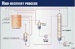
Similarly, replacement of the cold separator of the double-expander process with a column and a heat exchanger allows the vapor from the second expander to be refluxed (Fig. 6).
Optimization of column performance and judicious use of heat-exchanger area to improve process efficiency allowed propane recovery to be increased 90% with no appreciable increase in sales-gas compression power.
Reduction of process operating pressure and temperature enabled an increase in propane recovery to 95%. The lower pressure resulted in an increase of 10% in compression power.
Then, by careful optimization of overall energy integration and especially incorporating all heating and cooling duties into multistream plate-fin exchanger duties, it was possible to maintain 95% propane recovery while bringing the power consumption back to that incurred for the double-expander flowsheet.
The 95% propane recovery flowsheet with the double-expander concept was taken forward to pre-engineering and detailed engineering (OGJ, July 27, 1998, p. 77). Although it draws on operating experience and patents, especially those using reflux exchangers, it is sufficiently novel to be the basis of a recent patent application.
Applications
The concepts discussed are appropriate for plants processing dense-phase natural gas or for lower feed pressure. There is less justification for using two expanders in series at lower feed pressure, but improved rectification with a reflux exchanger or a high-pressure column will normally be cost-effective, especially on large plants processing more than 100 MMscfd.
For very high NGL recovery, the savings in compression cost easily outweigh the cost of the additional equipment.
The techniques discussed here are equally valid for revamps (OGJ, Apr. 20, 1998, p. 43). Several studies have been carried out that follow the methodology of increasing process efficiency and performance in steps until the optimum process modifications are found from detailed costing exercises.
As turboexpander plants are inherently inefficient due to the large temperature difference between the expander outlet and the feed-gas separator, there is often much scope for improvement.
Acknowledgments
The authors acknowledge the permission of the management of Costain Oil, Gas & Process Ltd., Enron Power Operations Ltd., and Statoil for permission to publish this article.
References
1. Tomlinson, T.R., "The Enron Teesside Gas Processing Plant," IChemE/GPA Oil and Gas Processing Conference, Poole, UK, Sept. 24, 1992.
2. Oliver, J.R., "Teesside Gas Processing Plant: From Green Field Site to Commercial Operation," IChemE/GPA Power from Gas Conference, Teesside, Sept. 23, 1993.
3. Tomlinson, T.R., Finn, A.J., and Halford, L., "The Enron Teesside Gas Processing Plant," Hydrocarbon Technology International Quarterly, Autumn 1994, p. 127.
4. Oliver, J.R., "The Development of Enron's Teesside Gas Processing Facilities," GPA 12th Continental Meeting, Semmering, Austria, May 31-June 2, 1995.
5. Connell, D.E., Horth, P., and Powell, R.H.W., "Optimum Propane Recovery for a NW Europe Gas Terminal," 72nd GPA Annual Convention, San Antonio, Mar. 15-17, 1993.
6. Lillared, J.K., and Nicol, G., "An Operating History of Turboexpanders in the Supercritical Fluid Regime," 73rd GPA Annual Convention, New Orleans, Mar. 6-9 1994.
7. Limb, D.I., and Czarnecki, B.A., "The PetroFlux Process for NGL Recovery: Experience to Date and New Developments," 66th GPA Annual Convention, Denver, Mar. 16-18, 1987.
8. Tomlinson, T.R., and Limb, D.I., "Propane Recovery, Reflux-Exchange Process," Encyclopedia of Chemical Processing and Design, No. 45, ed. J.J. McKetta, (New York: Marcel Dekker, 1993).
9. US Patent 4,846,863, T.R.Tomlinson and B.A.Czarnecki.
The Authors
Adrian Finn is technology development manager with Costain Oil, Gas & Process Ltd., Manchester, UK. He has spent 17 years with Costain mainly as a process engineer on gas processing projects. He holds a BScTech in chemical engineering and fuel technology from Sheffield University and an MS from Leeds University (both UK). Finn is a fellow of the Institution of Chemical Engineers and is a chartered engineer in the UK.
Terry Tomlinson is business development director for Costain Oil, Gas & Process Ltd., Manchester. Since receiving his BS (1974) in chemical engineering from Leeds University, he has worked on the process design and development of oil, gas, and processing plants. He is a Fellow of the Institution of Chemical Engineers and is a chartered engineer in the UK.
Grant Johnson is a process engineer with Costain Oil, Gas & Process Ltd., Manchester. Since joining Costain in 1997, he has worked on a number of conceptual and frontend design projects in natural gas liquefaction and nitrogen rejection. He holds BA and MEng degrees in chemical engineering from the University of Cambridge.
