Equations predict drill-pipe fatigue in Middle East operations
Lubinski's modified equations can be used to predict drill pipe fatigue damage in horizontal and directional wells.
During drilling of horizontal wells, an abnormal amount of tubular failures, typically in the form of cracks, occurred in the drill pipe and heavy-weight drill pipe (HWDP) used by land rigs operating in the Middle East.
The abnormality of these failures prompted investigations to establish the cause.
Time-of-failure
Drill pipe should achieve a life expectancy of 300,000 to 350,000 ft within 13,000 to 14,000 rotating hr. Yet the cumulative footage to time-of-failure for a land-rig case study achieved only 177,000 ft over an interval of 8,000 rotating hr. Furthermore, in many other cases, the cumulative footage of the HWDP did not even exceed 32,000 ft.
These factors were behind a decision to look at the actual well designs employed in the particular land rig's individual well programs, mainly at the planned build rates and length of horizontal sections required by various programs.
Mechanical limits
The goal of horizontal drilling is to enhance production or injection by placing longer horizontal sections within the reservoir. The optimum length for a horizontal hole is reached when the incremental cost of additional length becomes greater than the value of production from the additional length.
Thus, because productive performance continues to increase with increasing length, the optimum length is probably close to the maximum length that can be successfully drilled.1
The mechanical limits for horizontal holes are primarily related to the length of the radii, of which three types are to be considered:2 3
- Short-radius horizontal wells using special equipment to achieve build-up rates (BUR) of 1.5 to 3°/ft. The radii of this group of wells are 20 to 40 ft with most of wellbore in the vertical mode.
- Medium-radius horizontal wells using flexible downhole motors to achieve BURs of 8 to 20°/100 ft. The radii of these well types are 300-700 ft.
- Long-radius horizontal wells employ standard rotary-drilling assemblies and steerable systems to generate the curve and to drill the horizontal section. It has BURs of 2 to 6°/100 ft. The radii of these well types are more than 1,000 ft.
In many Arabian Gulf countries, most horizontal wells are drilled with the long or medium-radius curvatures.
Advantages
Horizontal wellbores can achieve production rates 20 times greater than comparable vertical or deviated wells with deviated angles up to 45°. Usually, an improvement of only about 2 to 2.5 times the productivity is economically sufficient for drilling a horizontal well.
The major reason for such improvement is that a horizontal wellbore increases exposure to the producing zone. Other advantages include:
- Reduced pressure drops and fluid velocities around the wellbore.
- Minimized water and gas coning.
- Accelerated production or injection rates.
- Increased chance of higher ultimate recovery.
Well profile
The selection of a horizontal well profile depends on the:
- Kick-off point (KOP).
- BUR.
- Tangent section.
The KOP, or the starting point of the curve, must be taken into consideration during selection of directional apparatus. Furthermore, KOP can be influenced by different factors including the:
- BUR.
- Lithology. In soft formations, the build up should be performed very slowly to avoid formation wash out. In such formations, low bit weights should be applied.
In hard formations, the building of angle is more effective as maximum bit weight may be applied to produce the response required. - Directional length considerations. The amount of open hole during directional drilling should be minimized.
BUR and tangent selection must be designed so as to provide sufficient horizontal displacement to reach the target entry point. This will allow variations in true vertical depth (TVD) due to geological uncertainties while providing a straight wellbore for casing shoe and completion equipment.
BHA
Due to differences in the forces and stresses applied to the drillstring and due to the geometry of horizontal wells, the bottomhole assembly (BHA) design is different for horizontal and vertical drilling applications. The main BHA component in horizontal drilling consists of the downhole motor used in both the build-up and horizontal sections.
The BHA can reduce the energy of the interaction between the rotating drillstring and the wellbore as well as reduce drillstring wear. The typical steerable-motor BHA used in long and medium-radius horizontal wells consists of the drill bit, adjustable positive displacement motor (PDM), flex nonmagnetic collar, measurement-while-drilling (MWD) hang-off sub, short flex collar, one joint of HWDP, drilling jar, two joints HWDP, and drill pipe.
When designing the the BHA, the loads and stresses affecting the drillstring should be eliminated or minimized. Some of the forces and stresses that act on the drillstring include axial loads, friction (axial and tangent), torque, side forces, hydrostatic pressure, and bending moment. In the build section, side forces and bending stresses dominate.
The bending stress increases under large loads and along the contact length of the drill pipe and wellbore wall. Lubinski recognized that drill pipe under tension in a dogleg develops bending stresses.4 5
These stresses become greater than those associated with drill-pipe bending in the hole without tension. Lubinski has studied three configurations regarding drill-pipe contact with the wellbore wall:
- No tube contact.
- "Point" tube contact.
- "Arc" tube contact.
As a result, design graphs based on his solution have been published.6 These cases can occur either by tensile or compressive axial loads.7 8 With increasing axial loads, the tube contact will change from no tube-contact to "point" tube-contact and further increase will lead to "arc" tube-contact.
Drilling procedure
The typical well configuration for this case study includes a vertical section, 20-in. conductor pipe, 171/2-in. surface hole, 121/4-in. intermediate hole, the build curve, and 81/2-in. production hole section. Polycrystalline diamond compact (PDC) bits are utilized on high-performance motors with adjustable bends to drill the build curve.
Tricone bits are then used to drill the 81/2-in. horizontal hole sections. The planned DLSs are usually 7°/100 ft. The well programs for the land rig, however, have been changed to drill multilateral wells with higher-than-planned BURs.
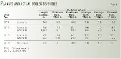
Table 1 shows the planned doglegs vs. actual doglegs experienced with the drillstring with all wells traversing 0 to plus or minus 90°.
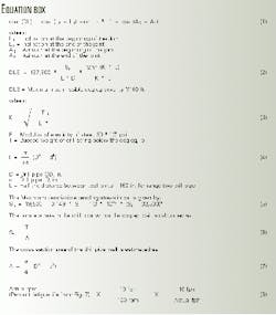
The Dogleg severity in Table 1 is calculated with Equation 1 (see Equation box). All build sections were drilled in the oriented sliding mode with bit rotation provided exclusively by the motor. Thus, the oriented sliding mode produces changes in inclination or azimuth changes without drillstring rotation.
A reaming run, however, was conducted using a roller reamer, HWDP, and drill pipe, which were rotated through the section at 50 rpm for a period of 12 hr in order to remove the ledges and to ensure that the 7-in. casing passed to bottom during the casing run.
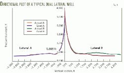
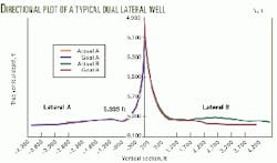
Thereafter, the string was rotated more often than slid within the 3,000-ft long horizontal section. This means that at well TD, about 4,000 ft of drill pipes were being rotated through the KOP and all the varying degrees of DLS (Table 1, Fig. 1).
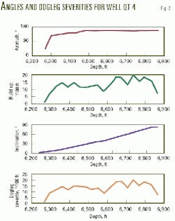
As Table 1 shows, the planned DLSs for all laterals were exceeded with one exception-Lateral B in well QT 2. This equates to 83% of the deviated sections. Fig. 2 presents the build up, azimuth, inclination, and dogleg for well QT 4, providing a typical example for the other wells.
Excessive BURs
There may be several causes of excessive build rates. However, the most common cause is formation thickness. The top of the formation was penetrated in many cases shallower than the predicted well program.
This is a frequent occurrence in the field. Another reason is that the Hith formation, which is where the KOP is located, is thought to be consolidated. In reality, however, this formation can be unconsolidated, especially at the bottom of the Arab C transition zone where build rates can suffer drastically if this occurs.
Bit selection and the adjustment of the bent housing on the motor are also reasons for failing to achieve planned BURs. Experience has shown that PDC bits can reduce the BUR by an average of 10% as compared to tricone bits.
This should be taken into consideration during use of a PDC bit. The selected PDC bit must have a short gauge for improved steerability where BURs are higher than 7°/100 ft.
Moreover, simultaneous build up and turning in the build section is not recommended. Nevertheless, if toolface turning is required to correct the azimuth, this should be done first to avoid excessive time and cost.
One of the inherent problems for high BUR wells is that when one or more of the above-mentioned problems occur, the increase in the build rate becomes quite noticeable. This can lead to other problems such as drill-pipe fatigue, missed targets, and shortened vertical sections. Consequently, it becomes necessary to plug back the drilled section.
Cracks
Most cracks found in the drillstrings were:
- Oriented normal to the longitudinal axis.
- Distributed around the circumference of the pipe body.
- Positioned close to the tool joints.
These features are often called washouts and are initiated along the OD in the transition region between the taper and the tube, where high stresses are expected.
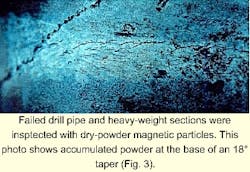
Dry-powder magnetic particle inspection was used to examine each section of the failed drill pipe as well as the HWDP (Fig. 3). While no cracks could be seen in some sections, the magnetic particle inspection revealed numerous "suspects," ranging in length from 1/16 to 3/8 in. at the base of the 18° taper (Fig. 4).
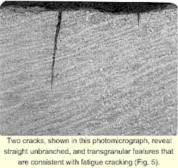
Fig. 5 shows a section taken through some of the joints that were mounted, polished, and etched for metallographic examination. Two cracks can be seen in the cross section side-by-side in the photomicrograph.
The cracks formed straight, unbranched, and transgranular features, consistent with fatigue cracking. Because there were multiple parallel cracks distributed almost all the way around the pipe, the initiation of these cracks was most likely caused by cyclic tension and compressive alternation in a heavy bending process. Fatigue provides the major driving force for crack-tip propagation.
Fatigue Analysis
Drillstring failures guided King Saud University to calculate the maximum permissible DLS and the maximum permissible bending stress with respect to possible fatigue of drill pipe and HWDP.4-7 Lubinski's equations with modifications (API RP 7G) were used to calculate the allowable bending stress in the outer fiber of the wall of the drill pipe (Equations 2-7).
The tensile stress should be less than or equal to 67,000 psi for the equations to be applicable.
The amount of fatigue damage depends on:
- The tensile load in the drill pipe at the dogleg.
- The severity of the dogleg.
- The number of turns of drill pipe while it is within the dogleg.
- The mechanical dimensions and metallurgy of the drill pipe.
The actual location of the dogleg is important because the buoyed weight below the dogleg affects the bending stress of the drill pipe. For instance, the bending stress is calculated for the case of well QT3 using the modified equations.
In this case, the planned DLS is 10°/100 ft at a total string length of 4,000 ft below the dogleg. The calculated bending stress for this example is 17,125 psi. Equation 2 gives the maximum permissible bending stress for a DLS of 10°/100 ft, which should not exceed 15,810 psi. Thus, the actual bending stress at even 10°/100 ft was already exceeded.
However, the actual average for QT 3 was 12.3°/100 ft. This has the effect of pushing the bending stress beyond its limit. The calculated bending stress with a DLS of 12.3°/100 ft is 19,446 psi, or 13% above the limit.
Yet the effect of high DLS has an even greater effect on the bending stress within the deviated section. For example, in well QT 3, the maximum dogleg was 17°/100 ft located at 6,335 ft measured depth.
Thus, the total length of the string below the DLS was 3,585 ft and the calculated maximum permissible bending stress was 26,026 psi. This shows a 52% increase in bending stress. The foregoing calculations showed that drill-pipe fatigue occurs within the drillstring due to overstressed drill pipe.
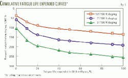
Moreover, the number of drill-pipe turns within the dogleg contributes to shortened tubular life. Hansford and Lubinski have developed a method for estimating the cumulative fatigue life in noncorrosive and extremely corrosive environments, assuming a rotary speed of 100 rpm drilling at 10 fph.9
Fig. 6 presents cumulative fatigue life expended curves for drilling in a non-corrosive environment and Equation 8 can be used for other penetration rates and rotary speeds.
If the DLS equals 10°/100 ft, and the buoyant weight below the dogleg is 75,000 lb, the fatigue life expended will be about 15% with a rotary speed of 100 rpm and penetration rate of 10 fph.
References 9 and 10 describe a typical drillpipe S/N curve for grade E drill pipe where the S/N curve defines the relationship between the cyclic bending stress and the rotating cycle before fatigue failure.
References
- Schuh, F.J., "Horizontal Well Planning-Build Curve Design," SPE Paper No. 20150, presented at the Centennial Symposium Petroleum Technology Into the Second Century, Socorro, NM, Oct. 16-19, (1989).
- Sperry Sun Drilling Services "Directional Drilling Handbook" Document Number: TMHD 2004, 1998.
- Amoco, EPTG Drilling Technology Teams, Training to Reduce Unscheduled Events, Third Edition, 1996.
- Lubinski, A., "Maximum Permissible Dogleg in Rotary Boreholes," Journal of Petroleum Technology (JPT), February 1961.
- Lubinski, A., "Fatigue of Range 3 Drill Pipe," Revue de L'Institute Francias du Petrole, March 1977.
- American Petroleum Institute, API RP 7G, Recommended Practice for Drill Stem Design and Operating Limits, 15th Edition, Washington, DC, January 1995.
- Schuh, F.J., " The Critical Buckling Force and Stresses for Pipe in Inclined Curved Boreholes," SPE/IADC Paper No. 21942, presented at 1991 SPE/IADC Drilling Conference held in Amsterdam, Mar. 11-14, 1991.
- Paslay, R., and Cernocky, E.P., " Bending Stress Magnification in Constant Curvature Doglegs With Impact on Drillstring and Casing," SPE Paper No. 22547, presented at the 66th annual Technical Conference and Exhibition of the Society of Petroleum Engineers, Dallas, Oct. 6-9, 1991.
- Hansford, J.E., and Lubinski, A., "Effect of Drilling Vessel Pitch or Roll on Kelly and Drill Pipe Fatigue," JPT, January 1964.
- Grondin, G.Y., and Kulak G.L., "Fatigue Testing of Drillpipe," SPE Drilling and Completion, SPE Paper No. 24224, June 1994.
The author
Mohammed M. Amro is an assistant professor in the petroleum engineering department at King Saud University, Saudi Arabia. He joined the faculty in January 1999. Previously, Amro worked for the German Petroleum Institute and Qatar Drilling Co. He holds a BS, MS, and PhD in petroleum ingineering from Technical University of Clausthal, Germany. He is a member of SPE and DGMK, Germany.
