Water-condensation rate critical in predicting, preventing TLC in wet-gas lines
TOP-OF-LINE CORROSION-1
This first of two articles on top-of-line (TLC) pipeline corrosion demonstrates that TLC in wet-gas pipelines correlates with the water-condensation rate (WCR).
A model to calculate WCR along the pipe profile and evaluate the risk of TLC is presented.
The conclusion next week indicates how corrosion-prediction models can be updated and presents remedial actions for the preventing TLC.
Research reported on here evaluated the risk of TLC rate for gas lines from three different fields and obtained a good agreement between inspection pigging-UT inspection records and evaluated WCRs.
The evaluation confirmed that, in wet gas lines, there is a critical WCR above which TLC takes place. When this limit is exceeded, the TLC rate increases with increasing WCR and increasing demand of iron for saturating/super-saturating the condensed water.
The effluent temperature, the flow rate, and the content in organic acids, if present, strongly influence the TLC rate. The critical WCR in wet multiphase gas lines is between 0.15 and 0.25 ml/(sq m.sec), depending on the water-wetted portion of the pipe surface that was considered for the calculation.
Top-of-line corrosion can be prevented by application of heat-insulated coatings, use of cladded pipes, or by pipe burial at an appropriate depth.
TLC conditions
Published TLC cases1-5 and inspection results of gas lines operated by Totalfina Exploration & Production, Paris, indicate the conditions promoting TLC can be summarized as follows:
- Single-phase wet gas line or multiphase gas line with stratified flow regime.
- High effluent temperature with external cooling by river water, seawater, or cold air.
- Produced water containing a significant amount (300 to 3,000 ppm) of organic acids.
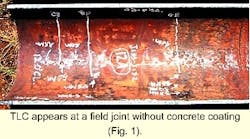
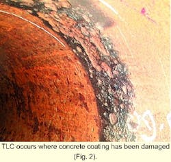
- Unburied pipe (onshore or offshore), pipe sections subject to upheaval buckling exposed to river water or seawater, field joints or doglegs with thin anticorrosion coating without concrete (offshore) or heat insulation (Fig. 1), and pipe sections with damaged concrete coating (Fig. 2).
Acceleration of the corrosion results from competition between the WCR and corrosion rate; the former tends to dilute the condensed water, the latter to saturate it.
The presence of organic acids tends to initiate or accelerate localized corrosion. Predicting and controlling TLC require a simulation program for the WCR calculation, which can also be used for evaluating different such preventive solutions as pipe burial, heat insulation, and pipe cladding.
The model developed and explained here was tested by comparing the estimated water condensation profile with the line-inspection results. This article discusses the details of this program, its validation, and its use for the evaluation of TLC control methods.
Water-condensation rate
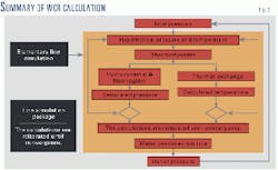
An integrated module is used for the simulation of multiphase flow along the wet-gas lines, as shown on Fig. 3:
- A thermodynamic package calculates all physical properties of the produced effluent required for the estimation of the overall heat-transfer coefficient and used by the hydrodynamic package. The effluent is defined by means of its composition and total flow rate.
The program assumes that the different phases of the transported fluid are in thermodynamic equilibrium. Although the thermodynamic model can support a large set of equations of state, the Soave-Redlich-Kwong (SRK) equation is generally used for this type of simulation.
The program takes into account the possible solubility of hydrocarbons, acid, or alcohols in the water. The thermodynamic package also performs the build-up of the effluent matching the produced gas and oil rates at separator reference conditions, which are usually the test separator or the inlet-separator conditions (Fig. 4).
- A hydrodynamic package, in this case the Tacite6 two-phase hydrodynamic model, determines steady-state flow conditions (flow regime, pressure drop, liquid holdup).
This mechanistic "drift flux" model solves the mass and momentum balance equations and the energy equation at any given point of the line.
It supports all types of two-phase flow regimes encountered in oil and gas pipelines, depending on the velocities of the phases and on the slope: annular, stratified wavy and stratified smooth, dispersed flow and slug flow, treated by an average "cell" approach.
The transitions between the different flow regimes are solved via mechanistic criteria.
- A thermal exchange package relates the radial heat transfer in a pipeline, at a given location and in steady-state flow, to the overall heat-transfer coefficient (U0; Equation 1 in the accompanying box).
- A line-simulation package determines the temperature, pressure, and WCR profiles along the length of the line.
The geometrical profile of the line, established from bathymetric data or routing survey, is divided into several sections. The length of these sections depends, first, on the distribution of the slopes and heat-transfer parameters along the profile.
Then, a fine meshing is applied to the pipe sections where TLC is suspected to occur, typically along the first few kilometers or on river crossing, whereas only a coarse meshing is kept elsewhere in the line, unless the internal convergence criteria of the line simulation package initiate a finer segmentation.
After calculation of the temperature and pressure at a given point (or elementary pipe length) of the line, the program separates out the different phases. The program saturates both condensate and gas phases in water, if any are present.
The amount of condensed water (ml/sec) dropped out from the gas is determined by material balance of the saturation water of the gas phase over the elementary pipe length.
Two options are available to calculate the WCR (ml/[sq m.sec]) over the inner-wall surface of the elementary pipe length "wetted" by the gas phase.
A gas-wetted perimeter of 50% of the pipeline perimeter agrees with the concentration of the pits between the 9 o'clock position and the 3 o'clock position in the inspection pigging records.
A gas-wetted perimeter, derived from the liquid hold up determined by the hydrodynamic model, was also considered in some cases. This later gas-wetted perimeter, generally higher than 50%, corresponds to a flat interface, whereas the first option considers a concave interface more consistent with high gas-flow velocities.
In its present status, this approach does not yet allow:
- Determination of any segregation and slippage between the oil-condensate and the water phases. The hydrodynamic model treats condensate and the free water (produced and condensed) as an homogeneous mixture.
- Differentiation between the temperature of the gas phase and the temperature of the liquid phase.
Model tuning
The model is tuned to match available measurements of flow rate, pressure, and temperature. The pipe-wall roughness is adjusted to fit the measured pressure drop, whereas the external convection coefficient is adjusted to fit the temperature of the effluent.
It is also possible to adjust the predicted liquid viscosity to fit measured data. Indeed, the thermodynamic models are known to under-evaluate oil viscosity, and it is generally recommended to use measured viscosity, when available, to perform pressure-drop simulations.
Validation for TLC prediction
WCRs were calculated along four lines for which the occurrence of TLC was already confirmed by inspection pigging. Two other lines that were not subject to TLC were also simulated to confirm that the model predicts low condensation rates in these cases.
Based on the operating conditions and using the integrated thermo-hydrodynamic approach explained above, a model of the pipeline was built for each case and tuned to match with field measurements.
- Line A: TLC confirmed. Details of this multiphase wet-gas line (Tunu field, Indonesia) in stratified flow and crossing a river at several locations have already been published.5
The acetic-acid content of produced water is 300 to 2,100 ppm. Even though the corrosion-monitoring systems have shown negligible internal corrosion rates, inspection pigging indicated severe internal TLC, in three locations, after 6 years of service.
The lengths of the corroded pipe sections vary between 10 and 100 m, at locations where the pipes were unburied, subject to heavy cooling in direct contact with river water, thus to heavy water condensation.
A pipe portion was removed. Visual inspection and laboratory examination confirmed the proposed explanation.
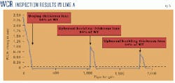
Fig. 5 gives the WCRs. The zones where the U0 is almost nil are buried pipe sections, corresponding to very low WCR (0.01 ml/[sq m.sec]). The WCR is quite high at locations where TLC was detected, first in the dogleg and following two corroded sections at the locations where upheaval buckling occurred.
The WCR trend correlates the inspection results, although it is not possible to quantify a critical WCR in this case. The pipe-thickness loss given by inspection pigging indicates that the corrosion rate is independent of the WCR because the corrosion rates at three locations are quite similar to different condensation rates.
The actual external cooling rate may be different at these three locations, whereas the same cooling rate was used for this study or upheaval buckling occurred at different times at these two locations.
- Line B: TLC confirmed. This is a 14-in. multiphase gas line with stratified flow regime, except in the risers where annular flow occurs. It was coated with 2 mm of polypropylene and no concrete coating.
The inlet temperature is about 85-95° C. The acetic-acid content of the formation water is up to 2,000 ppm.
Inspection pigging, after 5 years of production, indicated that TLC affects the first kilometer of the line. The corrosion is at the top of the line, between 9 o'clock and 3 o'clock positions at the dogleg and tends to concentrate at the 12 o'clock position by the end of the corroded section (about 1 km from the dogleg) with decrease of the corrosion rate.
The pits are deeper between kilometer point (KP) 0.1 and 0.4; then the pit depths decrease with the length.
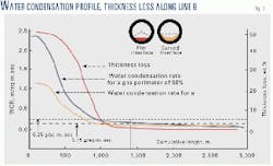
Fig. 6 shows the WCRs against the cumulative length and also reports the inspection results.
Curve A would be the WCR for a gas phase limited to 50% of the pipeline perimeter corresponding to a concave interface more consistent with high gas-flow rates and with the concentration of the pits between the 9 o'clock position and the 3 o'clock position in the inspection report.
Curve B represents the WCR calculated for a gas-wetted perimeter of 84-93%, corresponding to a flat gas-liquid interface. Two thresholds of WCR provide an acceptable level of thickness loss by TLC:
- 0.15 ml/(sq m.sec) with a gas perimeter calculated without compensation for the gas-liquid interface curvature.
- 0.25 ml/(sq m.sec) with a gas perimeter of 50% total perimeter.
These results provide a first evaluation of the critical WCR.
- Line C: TLC confirmed. This line is identical to Line B in diameter and coating configuration.
The inspection pigging indicated a concentration of pits between the 10 o'clock position and the 2 o'clock position. The highest thickness losses (about 30-50% of WT) are detected along the first 400 m of the line.
This concentration decreases along the line until KP 1.5; then a few localized shallow pits (depths around 10 to 20% of WT) were identified. Compared to Line B, the pits are less deep and less numerous.
This line was operated during the last 5 years at flow rates less than 1 million std. cu m/day. As the operating pressures were similar on both inspected Line B and Line C, the smaller TLC on the Line C can be explained by the operation at lower gas-flow rate and a lower temperature of the effluent (60-70° C).
The WCR profile compared to thickness-loss profile along Line C is very similar to that for Line B.
- Line D: TLC confirmed. This is an 18-in. offshore multiphase gas line that has been operated for 4 years at flow rates from 2 to 4.5 million std. cu m/day in stratified flow regime and with an inlet temperature 80-91° C.
It was coated with 2 mm of polypropylene and no concrete coating. The acetic-acid content of the formation water is up to 700 ppm.
Inspection pigging after fewer than 3 years of production indicated that TLC has affected the first 2 km of the line: 88% of pits are upstream of KP 1.0 with a peak corrosion rate of 2 mm/year; 12% remaining pits are between KP 1.5 and 2.0 with a peak corrosion rate of 1.1 mm/year. There is a virtual absence of defects between KP 1.0 and 1.5.
For the first time, metal losses were reported in the riser close to the dogleg. The slight riser slope, which favors stratified flow instead of annular flow, may explain the presence of such defects.
A first model, based on as-built data from the construction drawings, was used to determine the WCR profile along this line. The WCR thus calculated would progressively decrease to 0.25 ml/(sq m.sec), considered as the critical WCR in this case, within the first kilometer of the line and then would thereafter remain below this threshold value.
It was then suspected that this line could have been progressively buried, under its own weight, into the very soft clay on which it was originally laid. An accurate survey of the burial status of the line indicated that it was indeed partially or completely buried at several locations along its routing, especially between KP 1.0 and KP 1.5.
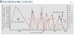
Once updated to take the detailed burial status of the line into account, the simulation model showed a very good match between the WCR profile and the locations of the corrosion pits. Fig. 7 shows the first 500 m of pipe.
High WCR corresponds to unburied or partially buried sections of the line, whereas low WCR is predicted where the line is totally buried and no or very low TLC recorded. Moreover, the WRC profile meets the threshold value of 0.25 ml/(sq m.sec) after 2 km.
This detailed analysis shows that the natural burial of the line controls TLC locally, by preventing high water condensation, but shifts the critical conditions that favor corrosion further downstream in the line. These results provide a second validation of the CWCR.
- Lines E and F: No TLC detected. The gas in these 8-in. lines contains H2S and CO2 (ABK field, UAE). The lengths of Lines E and F are about 5,000 and 3,000 m, respectively.
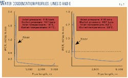
The gas flow rates in these lines are about 1.5-1.8 million std. cu m/day, with respective inlet and outlet pressures of 116 bar and 107 bar. The inlet and outlet temperatures are 63° C. and 29° C. for Line E and 74° C. and 41° C. for Line F. And the flow regime is stratified except in the inlet risers where annular flow occurs.
Both lines are coated with 5-mm thick coal-tar epoxy and 50 mm thick concrete. The riser coating is 12-mm thick neoprene. These lines have been in operation for about 12 years. Spot checks by ultrasonic scanning carried out at several locations showed no sign of TLC.
Fig. 8 shows the results of simulations performed to evaluate the TLC risk. The WCRs are less than 0.25 ml/(sq m.sec) in both lines, downstream of the riser. This confirms that below a critical WCR, TLC does not take place.
As there is no TLC detected and the condensation rate is low, the possible influence of H2S cannot be confirmed.
References
- Estavoyer, M., "Corrosion problems at Lacq sour gas field," in H2S corrosion in Oil and Gas Production (NACE: Houston, 1981) p. 905.
- Pailassa, R., Dieumegarde, M., and Estavoyer, M., "Corrosion control in the gathering system at Lacq sour gas field," in H2S Corrosion in Oil and Gas Production, (NACE: Houston, 1981), p. 860.
- Ho-Chung-Qui, D.F., and Willamson, A.I., "Corrosion experiences and inhibition practices in wet sour gas gathering systems," CORROSION/87, Mar. 9-13, 1987, San Francisco.
- Bich, N. N., and Szklarz, K.E., "Crossfield corrosion experience," CORROSION/88, Mar. 21-25, 1988, St. Louis.
- Gunaltun, Y.M., Supriyatman, D., and Jamaludin, A., "Top of line corrosion in multiphase gas lines. A case history," CORROSION/99, Apr. 25-30, 1999, Orlando.
- Dhulesia, H., and Lopez, D., "Critical Evaluation of Mechanistic Two-Phase Flow Pipeline and Well Simulation Models," SPE Annual Technical Conference, Denver, Oct. 6-9, 1996.
The authors-
Yves M. Gunaltun is a senior corrosion engineer at Total Exploration & Production, Technology Division, Paris. He was involved in Total projects 1982-86 as a corrosion engineer and was seconded to Zadco (UAE) in 1987 and to the QatarGas LNG project in Houston in 1992. He has been involved with all Total projects since 1993. Gunaltun holds a PhD from I.N.P.G. (France).
Dominique Larrey is senior process engineer and multiphase flow expert for TotalFina Exploration & Production, Paris, a position she has held since 1995. She joined TotalFina in 1982 as a process engineer after 3 years as a structural and civil engineer with Coyne Bellier. Larrey graduated from the Ecole Nationale des Ponts et Chauss
Based on a presentation to CORROSION/2000 (NACE), Mar. 26-31, 2000, Orlando.

