New load combination approach brings API 650 into line with ASCE 7

UPDATING API 650— Conclusion
American Petroleum Institute's pressure vessel and tank committee recently concluded a 5-year effort to revise Standard 650 that provides design rules for reasonable margins against failure of petroleum storage tanks due to loads imposed on them.
Results of this effort will be included in the latest (11th) edition of API 650, which the committee expects to be published in 2005. This second of two articles on those revisions addresses new load combinations; Part 1 (OGJ, Dec. 8, 2003, p. 58) addressed the individual loads.
Before the revisions, API 650 was reasonably successful in providing both safe and cost-effective tank designs, but it was right often for the wrong reasons. Despite the difficulties in changing long-held approaches, API made a nearly complete overhaul of its load provisions.
With revisions to API 650 discussed in these two articles, the standard now prescribes a more-accurate and rational approach to loads and load combinations, bringing API 650 into much closer conformity with American Society of Civil Engineers (ASCE) 7, the nationally recognized load standard.

null
Although the new load-combination design methods (discussed in this concluding article) will not typically result in drastic changes to tank components, the new approach allows API 650 to align with the standardized ASCE 7 strength-design methods and changes in the future easier as ASCE and other codes evolve.
Although the ASCE 7 methods for combining loads have been applied to most tank loads, ASCE 7 does not cover certain other specific design issues and failure modes, such as design of the frangible roofs for venting of excess internal pressure, settlement, thermal loads, and design of internal floating roofs.
Safety factors
Load combinations are written by providing factors on loads when certain combinations are considered, for example, 1.2D + 1.6L, used for the dead (D) and live (L) load combination in strength design.
Load combinations cannot be rationally set, however, unless safety factors as well as load factors are considered. As noted in Part 1 last week, factors on strength (safety factors) and factors on loads are simply opposite sides of the same coin.
Therefore, let's first examine 650's safety factors.
Some failures have more serious consequences than others. For example, shell rupture due to stress from stored liquid would spill the tank contents, while wind damaging the tank roof would not.
API 650 accounts for this by setting safety factors commensurate with failure consequences. For example, API 650 3.6.2.1 prescribes a safety factor of 2.5 for shell rupture due to pressure from a full tank of stored liquid, while the API 650 3.11.2 safety factor for wind overturning an empty tank is 1.5.
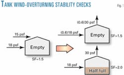
Safety factors can be used to address tank wind overturning stability. For a full tank, a safety factor of 2.5 is appropriate because overturning would presumably rupture the tank and spill its entire contents.
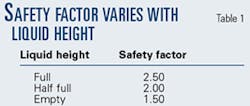
For liquid levels between empty and full, a safety factor proportionate to the liquid level can be rationalized. For example, the safety factor required for a half-full tank is the average of the safety factors for empty and full tanks, or (1.5 + 2.5)/2 = 2.0 (Table 1).
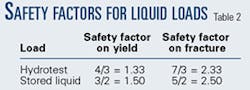
Hydrotest loads (Ht), because they are infrequent (only at initial construction of the tank and after major repairs) and closely controlled, have lower safety factors than stored product (Table 2).
API 650 allows a one-third increase in allowable stresses (effectively decreasing the safety factor to three quarters of its normal value) for some components (e.g., anchor bolts and foundations) under wind or seismic load. This increase is not applied in all cases involving these loads, however.
It is not applied, for example, in the overturning stability check in Section 3.11.2 or explicitly included in the wind load checks on tank shell and wind girder. The reason for the increase is not given in API 650 and ASCE 7 prohibits it, except in two cases:
1. In allowable stress design, when more than one transient load (i.e., other than dead load) acts at the same time, the sum of the transient loads may be factored by 3/4. This has nearly the same effect as increasing the allowable stress by 1/3 because 1 + 1/3 = 4/3, the reciprocal of 3/4. (It's not exactly the same because stresses from dead loads are not reduced.)
The purpose of increasing the allowable stress is to account for the fact that it's unlikely that the wind and another transient load will both attain their maximum value simultaneously. Therefore, no allowable stress increase should be applied when only wind and dead load act.
2. Where "it can be demonstrated that such an increase is justified by structural behavior caused by rate or duration of load," increases may be used (ASCE 7 Section 2.4.1). This refers to materials with a significant difference in strength for short-term loads vs. long-term loads. This is true for wood (which has about one half the strength for a load applied for 10 years vs. its strength for a short duration load) but not steel used to build tanks.
Other reasons have been offered for an allowable stress increase for wind. One is that "wind is a comparatively rare occurrence." But the wind load has the same probability of occurring as the snow load (that is, once in 50 years). Another is that wind is "intermittent," "transient," or of "short duration." But this effect is accounted for by the gust factor (which is less than 1).
Yet another is that for some structures the direction of the maximum wind may not coincide with the direction in which the building is most vulnerable. For example, a rectangular building is most vulnerable when the wind is perpendicular to one face. This is the directionality factor discussed in the section on wind loads above.
A blanket 1/3 allowable stress increase for wind cannot be justified based on the principles of ASCE 7. A lower safety factor is, however, reasonable when failure would not have serious consequences. If, for example, an empty tank's anchors fail, no contents will be spilled, even though the tank might suffer significant damage, because there is nothing (or very little) in the tank to spill.
An anchor allowable stress of 80% of the yield strength as in E.6.2.3 for seismic loads represents a relatively low safety factor of 1.25. A low safety factor on anchor yielding is appropriate for a seismic load on a tank because, to avoid rupturing the tank, it is preferable to have the anchor yield before the anchor attachment to the shell fails.
Similarly, API 650 Section 3.10.3.4 provides for reduced safety factors (as low as 1.34) for cone-roof column buckling in limited cases (yield strength does not exceed 36 ksi, slenderness between 120 and 180). The reason for the limits is questionable because buckling of any column would probably not cause product release, but reduced safety factors for columns are consistent with the consequence of failure.
Load combinations
Although safety factors can account for the varying consequences of failure, factors on loads in load combinations can address the varying likelihood of loads acting concurrently. Different loads are likely to coincide at some time during the life of the tank. If a tank operates with external pressure, for example, it's likely that wind will blow on the tank while external pressure is acting. It's unlikely, however, that the external pressure and wind loads will be at their design values at the same time.
The new API 650 load combinations are based on the premise that a consistent level of risk is desired for all load combinations that may occur in the life of the structure. For example, the load combinations have been determined so that the risk of failure from a combination of hydrostatic pressure due to stored liquid and internal pressure will be the same as the risk of failure from a combination of wind and external pressure.
No load combination, however severe, will ensure that collapse will never occur because there is always a probability, however small, that the design loads will be exceeded or the strength overestimated. The assumption on which the new API 650 load combinations is based is that the risk of failure for any combination of loads is no more or less than for any other.
API recognized, however, that tanks built to recent API 650 editions have performed satisfactorily. While the intent was to align tank performance based on constant risk for components, therefore, some load combinations were adjusted to account for satisfactory historical performance.
Click here to view Load combinations and calculations in pdf.
The resulting, revised load combinations appear as the second set (Section B).

Grouping the combinations according to the tank component they affect yields Section G of the box.
Several simplifying adjustments were then made:
- The dead load factor can be rounded up to 1.0 from 0.9 with little effect on design because dead load stresses are generally small (the 20-psf minimum roof live load is much larger than the weight of common roof plate [7.6 psf]).
- The 1.1 factor on pressure, wind, and roof loads and the 0.9 factor on fluid loads can be rounded to 1.0 for simplicity. For wind, this is actually less of an approximation than it appears because ASCE rounded up the 1.6 ASCE load factor on wind from 1.53, and the 18-psf wind pressure is conservative. Also, this makes the new combinations consistent with 650's previous load combinations.
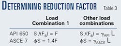
- ASCE 7's seismic load E is formulated for use with strength design and is about 1.5 times the API 650 allowable stress seismic load EAPI. So E = 1.5 EAPI ; since a 0.7 factor appears in all the terms of the combinations in the accompanying box involving E, they become 0.7(1.5 EAPI) = 1.0 EAPI in the combinations with seismic load. The dead and fluid load factors can be rounded from 0.9 to 1.0 so that 650 Appendix E need not be changed.