Linear-motor plunger pump increases lifting efficiency
Bojan Martinovic
Dusan Djekic
STC NIS Naftagas Ltd.
Novi Sad, Serbia
Dusan Danilovic
University of Belgrade
Belgrade, Serbia
Pavel Isaev
BORETS Service Serbia Ltd.
Zrenjanin, Serbia
Linear-motor driven plunger pumps (LMDPP) are most efficient at transforming mechanical energy to hydraulic work in low-producing and highly deviated wells. A field study in the Republic of Serbia compared power consumption between LMDPP, sucker-rod pumps (SRP), and electric submersible pumps (ESP). The study showed that the efficiency of all systems is affected by pumping speed as higher speeds correlate to higher loads and power consumption.
Pump failures
Over 5 million wells are on artificial lift worldwide. About 85% of wells in North America use artificial lift.1 SRP and ESP hold a 70% share of the global artificial lift market.2
Advantages of SRP over ESP include operation in slim holes and multiple completions, ease of operation, and ability to pump in wells with low pressure.3 They are one of the best solutions for vertical wells lifting high-temperature or viscous oils. Oils with a high content of paraffin and asphaltene, however, can cause problems for this equipment.4-7 The most common failure of SRP is the sucker rods themselves.8-10 Sucker rod failures were studied by Duan and Ding, and Zhao studied rod-tubing prediction methods to anticipate failures.11-13
ESPs use a dynamic-displacement multistage centrifugal pump connected to an electric submersible motor at the bottom of the unit. The pump is connected to a protector section that provides for safe operation of the unit. A pump intake or gas separator on top of the protector allows well fluids to enter the centrifugal pump and removes low quantities of free gas from the well stream. High impeller rotational speeds impart high centrifugal forces to the fluid, but lose kinetic energy in the diffuser where conversion from kinetic to pressure energy lifts fluid to surface.14
ESP advantages over SRP include high-volume lift from highly productive oil reservoirs with high water cut and application in deviated wells, which makes them suitable for offshore fields.15-18 Limitations to ESP include the need for high-voltage availability, difficulty executing multiple completions, and working in deep wells or high-temperature oil reservoirs.19 They also can degrade in sandy flows and high-viscosity fluids.20 21
LMDPP combines the advantages of ESP and SRP in that it uses a downhole motor like an ESP but with a pump consisting of a barrel, plunger, and valves like an SRP. Few studies, however, have been performed on LMDPP.22 23
China has more than 200 LMDPP installations, making it a leading user of the application, while Russia is performing initial trials.24 25 Mature oilfields in Northern Serbia equipped with ESPs and SRPs suffer from low dynamic pressure due to reservoir-pressure decline in highly deviated intervals, and LMDPPs were installed to address this.
LMDPP
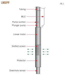
Fig. 1 shows typical configuration of a downhole LMDPP system consisting of a downhole sensor, protector, slotted screen, linear motor, plunger pump, and motor-lead extension (MLE). The unit uses a brushless synchronous permanent magnet motor (PMM) with magnets imbedded into or attached to the surface of the motor’s rotor instead of a squirrel cage.26 The motor is connected to the plunger pump via a shaft and provides reciprocating movement for lifting reservoir fluid to the surface. Several case studies of artificially lifted wells with ESP systems driven by PMM have shown that it is possible to increase system efficiency and reduce electrical consumption by 10-25% versus traditional motors.27 Data from 250 PMM applications showed that they have twice the service life of and lower operating temperatures than induction motors.28 PMMs also increase pump service life due to their higher efficiency.29 This technology is a key component of the LMDPP.
LMDPPs consist of three major operational components:
- A stationary oil-filled stator contains the motor to power the pump.
- A sliding rotor (slider) performs translational movements based on a set value at the control station and transmits it to the pump plunger.
- A protector compensates for motor-oil expansion caused by increasing temperature and equalizes pressure between formation fluid and the oil-filled stator.
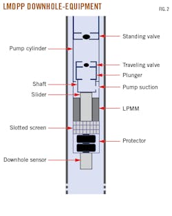
The plunger pump contains a hollow plunger with a traveling valve at its top and a standing valve above the plunger. This plunger pump is completely different in design than conventional sucker-rod pumps. The plunger is directly connected to the linear PMM on its lower side via a shaft that provides reciprocating movement to lift reservoir fluid to the surface. The plunger pump has standard API dimensions. Plunger stroke length is fixed and depends on plunger-pump capacity. Plunger-pump materials are selected based on conditions in the well. Fig. 2 shows a cross-section of the plunger pump and the complete downhole LMDPP.
Surface equipment
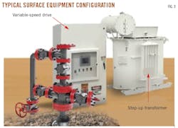
Fig. 3 shows typical surface equipment for an LMDPP system: a variable speed drive (VSD) and step-up transformer. VSD controls and protects the downhole LMDPP equipment in real time. A step-up transformer increases voltage from the existing power supply to the VSD to provide optimum voltage for operation of the LMDPP motor.
Operational parameter calculations
Because the pump is like a conventional SRP, a standard pump equation (Equation 1) calculates flow rate based on pump dimensions and reciprocal pumping speed.30 A standard SRP connects to the surface with rods at the point at which rotational movement of the motor controls pumping speed. The LMDPP plunger, however, connects to the downhole motor, which is controlled by the frequency of direct linear movement.
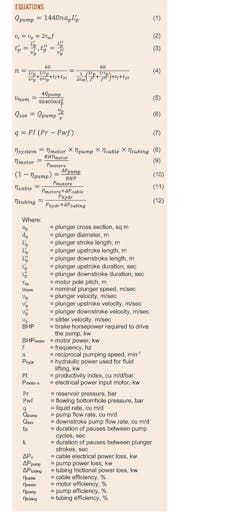
This setup requires a different calculation of operational parameters. Timasev described these calculations by acknowledging that the number of SRP plunger pump cycles (combination of one upstroke and one downstroke) does not always yield the same plunger speed and fluid production.31 This is a consequence of pauses made after plunger upstroke and downstroke, as well as after each complete pumping cycle. The speed of the slider determines average plunger speed and is represented by Equation 2. Duration of the plunger upstroke or downstroke is calculated by Equation 3.
Pump efficiency (Equation 4) depends on plunger-stroke length, plunger-stroke speed, and power frequency. The equation describes the dependence of the number of plunger pumping cycles on motor design, power frequency, and duration of intervals between plunger strokes.
Determining the operating range of frequency oscillation requires adjusting power frequency, plunger length during upstroke and downstroke, pause duration between plunger upstroke and downstroke, and pause duration between plunger pumping cycles. Nominal plunger speed corresponding to the plunger pump flow rate and frequency oscillation is calculated using Equation 5. The relationship between the flow rate through the traveling valve and the speed during plunger downstroke is given by Equation 6.
Field trial
A field trial was performed at Velebit, a mature oilfield in far north Serbia, to study performance of the LMDPP system. The field has been in continuous production since 1963 and has about 240 active wells with average fluid production of 15 cu m/day and 78% average water cut. About 75% of the wells are equipped with SRPs while the remaining 25% are equipped with ESPs. The field was chosen because more than 50% of the wells are characterized by:
- High wellbore deviation and dogleg severity.
- High power consumption of the ESP and SRP systems.
- Low productivity of ESP pumps operating in intermittent mode.
Well V-1 was selected for a comparative trial of the LMDPP system against ESP and SRP systems, parameters of which are presented in Table 1. The well is deviated and started production at the end of 2018 but suffers from low productivity. Kick-off point is 300 m from the surface with final deviation angle of 40°. Dogleg severity at kick-off point is 6°/30 m and progresses from 0.5°/30 m to 6°/30 m along the wellbore. Calculated productivity index (PI) is 0.7 cu m/day/bar (Equation 7).
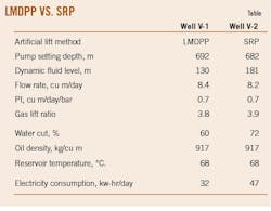
An ESP pump was initially used for the well. The ESP system operated continuously for 631 days and had high power consumption. With a decrease of reservoir pressure and PI, well production was too low for stable ESP operation. Frequent overheating and underloading shutdowns caused intermittent ESP operation which would stick the pump during restart due to deposition inside its stages. Deposition also resulted in malfunctioning check valves, which allowed fluid from the tubing to flow back into the well. The ESP was pulled and a LMDPP system installed.
The LMDPP system started pumping at 6 plunger strokes/min (spm) with the plunger stroke length fixed at 1,180 mm. Plunger downstroke speed was 0.4 m/sec to ensure the best possible filling of the pump, while plunger upstroke speed was 0.6 m/sec.
After the initial LMDPP operation period, pumping speed was increased to 7 spm, increasing plunger downstroke speed to 0.5 m/sec and plunger upstroke speed to 0.7 m/sec. Fig. 4 shows details from the installation of the LMDPP system on Well V-1.
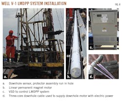
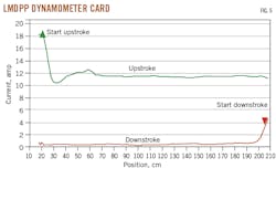
Fig. 5 represents the dynamometer card monitoring performance of the LMDPP system. Two curves on the card show dependence of the current in relation to the plunger position. The green curve represents plunger upstroke, and the red curve represents plunger downstroke. Maximum current is observed at the beginning of the plunger upstroke and at the beginning of the plunger downstroke. During plunger upstroke, the average value of the current was 12 amp, while the average value of the current during the plunger downstroke was 0.7 amp.
An electric meter built into the variable speed drive of the LMDPP system monitored electricity consumption, while a downhole sensor monitored dynamic fluid level, temperature, and pressure at the pump intake. A supervisory control and data acquisition system provided fine-tuning and monitoring of LMDPP operating parameters.
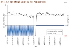
Stable production was achieved with the LMDPP system. Fig. 6 shows oil rates before and after LMDPP system installation (black line)and operating mode with “on” indicating that the well is working and “off” indicating well shut in (blue line).
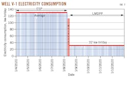
One of the most significant benefits of applying LMDPP in Velebit field is reduction of electricity consumption (Fig. 7). The ESP system recorded an average electricity consumption of about 130 kw-hr/day, while the LMDPP system registered an average of 32 kw-hr/day, about a 75% reduction.
Electrical consumption of Well V-2 equipped with SRP was compared with consumption of the LMDPP in Well V-1. The LMDPP system used 32% less energy than the SRP despite similar production between the wells.
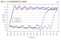
Additionally, gas interference in the rod-pump barrel in Well V-2 significantly reduced volumetric efficiency and occasionally led to gas locking in the pump. Fig. 8 shows two dynamometer cards from Well V-2. The first card represents the normal operation of the SRP system with high volumetric efficiency. The second card represents SRP operation with gas interference. Free gas at the pump intake reduces volumetric efficiency by as much as 30%.
The LMDPP system enables different plunger speeds during downstroke and upstroke, decreasing fluid slippage and neutralizing gas interference. The field trial showed that reducing plunger downstroke speed maximizes barrel filling and increasing upstroke speed quickly produces oil out of the tubing. The reduction in downstroke speed also resulted in a slight increase in dynamic fluid level which reduced gas influx at the pump intake.
Energy efficiency
Artificial lift methods applied at Velebit have different energy efficiencies. Overall efficiency of an artificial lift system is obtained from the total energy required to operate the system and the hydraulic power required to lift fluid to the surface. Overall system efficiency is calculated by Equation 8 combining individual efficiencies of system components.32
Estimating overall system efficiency requires considering energy losses in downhole and surface equipment. Based on the wide experience in application and detailed analysis of artificial lift systems at Velebit, energy losses are most noticeable along the tubing string, pump, motor, and electrical cable. These losses are mostly due to characteristics of the fluid and the wellbore. Individual efficiencies of system components depend on depth and geometry of the well, presence of free gas, fluid friction, and well productivity, among other factors. Individual LMDPP-component efficiencies are calculated by Equations 9-12. Equation 9 calculates motor efficiency, Equation 10 calculates pump efficiency, Equation 11 calculates cable efficiency, and Equation 12 calculates tubing efficiency.
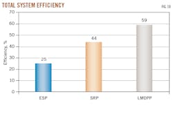
Fig. 9 shows results of the individual efficiencies of system components for ESP, SRP, and LMDPP systems. Fig. 10 compares total system efficiencies.
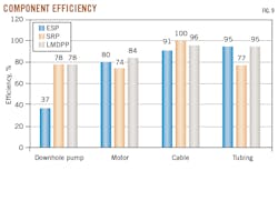
SRP and LMDPP systems have the same pump efficiency because they are volumetric pumps which have good performance on low-productivity wells. The ESP system, which has the best performance on high-rate wells, has low pump efficiency in these low-productivity wells due to low fluid inflow into the bottom of the well. Free gas traveling through the pumps negatively affects downhole pump efficiency in all three systems.
The LMDPP system’s downhole motor is most efficient because it is the only one that uses a permanent-magnet motor rather than an induction motor. The SRP system has maximum cable efficiency because its cable length is shorter than the three-core downhole cables used by ESP and LMDPP systems. These longer cables suffer from higher energy losses. ESP and LMDPP systems have high tubing efficiency compared with the SRP system, which has higher energy losses due to the sucker-rod string inside the tubing.
Of these three artificial lift methods, LMDPP showed the highest efficiency transforming mechanical energy to hydraulic work. Overall efficiency of all three systems was negatively affected by the high downhole losses in their power transmission systems. Additionally, losses were created by free gas entering the pumps, significantly reducing hydraulic output and overall efficiency.
Results also show that system efficiency is affected by pumping speed. With higher pumping speed, higher loads result in higher power consumption and lower system efficiency. Regardless of system, lower pumping speed increases system efficiency and reduces energy consumption.
References
- Olson, S., “Advancing Artificial Lift,” Oilfield Technologies, April 2019.
- Kimberlite International Oilfield Research, “Market Share Reports,” 2020.
- Bello, O., Dolberg, E.P., Teodoriu, C., Karami, H., and Devegowdva, D., “Transformation of academic teaching and research: Development of a highly automated experimental sucker rod pumping unit,” 107087, Journal of Petroleum Science and Engineering, Vol. 190, July 2020.
- Worth, D., Al-Safran, E., Choudhuri, A., and Al-Jasmi, A., “Assessment of artificial lift methods for a heavy oil field in Kuwait,” Journal of Petroleum Science and Engineering, Vol. 180, September 2019, pp. 835–843.
- Ghahfarokhi, A.K., Kharrat, R., and Bahram Soulgani, B.S., “Investigation of the asphaltene deposition along the flow of the oil in tubing: Experimental study and a parametric analysis,” Petroleum Science and Technology, Vol. 34, No. 10, June 24, 2016, pp. 884-890.
- Xu, B., “Influencing factors governing paraffin wax deposition of heavy oil and research on wellbore paraffin remover,” Petroleum Science and Technology, Vol. 36, No. 20, Aug. 17, 2018, pp. 1635-1641.
- Zhang, F., Ouyang, J., Feng, X., Zhang, H., and Xu, L., “Paraffin Deposition Mechanism and Paraffin Inhibition Technology for High-carbon Paraffin Crude Oil From the Kazakhstan PK Oilfield,” Petroleum Science and Technology, Vol. 32, No. 4, Dec. 23, 2014, pp. 488-496.
- Ko, P.L., Humphreys, K., and Matthews, C., “Reciprocating-sliding wear of sucker rods and production tubing in deviated oil wells,” Wear, Vol. 134, No. 1, November 1989, pp 13-28.
- Hedayat, A., Yannacopoulos, S., and Postlethwaite, J., “Wear and CO2 corrosion of steel couplings and tubing in heavy oil screw-pump wells,” Wear, Vol. 209, No. 1–2, August 1997, pp. 263–273.
- Hao, Z., Zhu, S., Pei, X., Huang, P., Tong, Z., Wang, B., and Li, D., “Submersible direct-drive progressing cavity pump rodless lifting technology,” Petroleum Exploration and Development, Vol. 46, No. 3, June 2019, pp. 621–628.
- Duan, D.L., Geng, Z., Jiang, S.L., and Li, S., “Failure mechanism of sucker rod coupling,” Engineering Failure Analysis, Vol. 36, January 2014, pp. 166–172.
- Ding, H., Zhang, A.B., Qi, D.T., Li, H.B., Ge, P.L., Qi, G.Q., Ding, N., Bai, Z.Q., and Fan, L., “Failure analysis of a sucker rod fracture in an oilfield,” 104300, Engineering Failure Analysis, Vol. 109, January 2020.
- Zhao, R., Li, J., Tao, Z., Liu, M., Shi, J., Xiong, C., Huang, H., Sun, C., Zhang, Y., and Zhang, X., “Research and Application of Rod/Tubing Wearing Prediction and Anti-Wear Method in Sucker Rod Pumping Wells,” SPE-194955-MS, SPE Middle East Oil and Gas Show and Conference, Manama, Bahrain, March 18-21, 2019.
- Takacs, G., “Design, Operations, and Maintenance,” Electrical Submersible Pumps Manual, Second Edition, Gulf Professional Publishing, 2017.
- Guo, B., Liu, X., and Tan, X., “Other Artificial Lift Methods,” Petroleum Production Engineering, second edition, 2017, pp. 603–635.
- Guo, B., Liu, X., and Tan, X., “Sucker Rod Pumping,” Petroleum Production Engineering, second edition, 2017, pp. 515–548.
- Naderi, A., Ghayyem, M.A., and Ashrafi, M., “Artificial Lift Selection in the Khesht Field,” Petroleum Science and Technology, Vol. 32, No. 15, May 19, 2014, pp. 1791-1799.
- Alarco´n, G.A., Torres, C.F., and Go´mez, L.E., “Global Optimization of Gas Allocation to a Group of Wells in Artificial Lift Using Nonlinear Constrained Programming,” Journal of Energy Resources Technology, Vol. 124, No. 4, Nov. 20, 2002, pp. 262–268.
- Langbauer, C., Pratscher, H.P., Ciufu, A.C., Hoy, M., Marschall, C., and Pongratz, R., “Electric submersible pump behavior for pumping non-Newtonian fluids,” 107910, Journal of Petroleum Science and Engineering, Vol. 195, December 2020.
- Zhu, H., Zhu, J., Rutter, R., and Zhang, H.-Q., “Experimental Study on Deteriorated Performance, Vibration, and Geometry Changes of an Electrical Submersible Pump Under Sand Water Flow Condition,” 082104, Journal of Energy Resources Technology, Vol. 143, No. 8, Nov. 19, 2020.
- Bulgarelli, N.A.V., Biazussi, J.L., Monte Verde, W., Perles, C.E., de Castro, M.S., and Bannwart, A.C., “Experimental investigation on the performance of Electrical Submersible Pump (ESP) operating with unstable water/oil emulsions,” 107900, Journal of Petroleum Science and Engineering, Vol. 197, February 2021.
- Wensheng, Z., Lin, W., Fengshan, W., Youquan, H., Gang, C., Fengwu, Z., Huaifeng, R., Junwen, G., Weiping, Z., Ling, L., and Xinmin, W., “A Unique Electrical Submersible Reciprocating Pumping (ESRP) System Design Applied in Unconventional Oil Field,” SPE-153123-MS, SPE Annual Technical Conference and Exhibition, San Antonio, Tex., Oct. 8-10, 2012.
- Guoxing, Z., Weishan, D., Qi, W., Lin, W., Fengshan, W., Yanan, S., Guoqing, W., Weike, W., and Yang, G., “Investigation and Application of Reciprocating Direct-Drive Electric Submersible Plunger Pump Lifting Technology,” SPE-186345-MS, SPE/IATMI Asia Pacific Oil & Gas Conference and Exhibition, Jakarta, Indonesia, Oct. 17-19, 2017.
- Zhu, S., Lei, D., Liu, H., Hao, Z., and Zhang, L., “Application of Low-Carbon, Rodless Artificial Lift in Low-Production, Low-Permeability Oilfields,” SPE-192071, SPE Asia Pacific Oil and Gas Conference and Exhibition, Brisbane, Australia, Oct. 23-25, 2018.
- Nonyava, S.A., Enikeev, R.M., Kurshev, A.V., Anpilogov, A.V., Nasretdinov, M.R., and Shubin, S.S., “Introduction and development of wells operation technology based on the use of electrical linear driven plunger pump in Bashneft PJSOC,” Neftyanoe Khozyaystvo-Oil Industry, Vol. 2, February 2019, pp. 66–71.
- Sagalovsky, V.I., Sagalovsky, A.V., Gmyzina, O.N., “Rotor of Submersible Electrical Drive for Pumping Installation in Oil Production”, Russian Patent RU 106809, 2011.
- Xiao, J.J. and Lastra, R., “Induction vs. Permanent-Magnet Motors for ESP Applications,” SPE Production & Operations, Vol. 34, No. 2, December 2018, pp. 385–393.
- Harris, D., English, J., and Leemasawatdigul, J., “Leveraging ESP Energy Efficiency with Permanent Magnet Motors,” SPE-185129-MS, SPE Electric Submersible Pump Symposium, The Woodlands, Tex., Apr. 24-28, 2017.
- Takacs, G., “Three inventions shaping the future of ESP technology,” 106330, Journal of Petroleum Science and Engineering, Vol. 182, November 2019.
- API RP 11L, “Recommended practice for design calculations for sucker rod pumping systems (conventional unit),” American Petroleum Institute, 14th ed., Washington, DC, 1988.
- Timashev, E.O., Urazakov, K.R., Volkov, M.G., Garifullin, A.R., Khalfin, R.S., and Brot, A.R., “Method of calculation for installations with electrical submersible reciprocating pump for oil production,” Neftyanoe Khozyaystvo - Oil Industry, Vol. 3, March 2020, pp. 72–76.
- Takacs, G., “Analysis and Optimization,” Electrical Submersible Pumps Manual, Gulf Professional Publishing, 2009, pp. 249–307.
The authors
Bojan Martinovic ([email protected]) is head of production technology in the science and technology center of Naftna Industrija Srbije (NIS) JSC. He holds an MS (2012) in petroleum engineering from the University of Belgrade, Serbia, where he is completing his PhD studies.
Dusan Djekic ([email protected]) is a senior production engineer in the production technology department in the science and technology center of NIS JSC. He holds an MS (2018) in petroleum engineering from the University of Belgrade.
Dusan Danilovic ([email protected]) is a professor with University of Belgrade’s faculty of mining and geology. He holds an MS (1997) and PhD (2001) from the University of Belgrade.
Pavel Isaev ([email protected]) is a production engineer at Borets Service Serbia Ltd. He holds an MS (2010) in petroleum engineering from the Ufa State Petroleum Technical University, Bashkortostan, Russia