Wellbore shielding system improves well integrity
Andrew Jordan
BJ Services
Tomball, Tex.
Lucas Albrighton
BJ Services
Denver
David Kulakofsky
Impact Fluid Solutions
Houston
Bryce Ballard
Ballard Petroleum
Billings, Mont.
Wellbore shielding (WBS) technology can help isolate the hydrocarbon formation from wellbore pressure, allowing successful placement of cement barriers. Knowledge of actual frac and pore pressure gradients is critical during the cement-design phase of well planning. Unfortunately, in exploration wells, engineers may have to estimate frac and pore pressure gradients. Cement circulation can fail due to uncertainties in these estimates. If errors in the engineering estimates cause lost circulation, at minimum the casing will not be supported. Resulting situations will require costly remedial work and, in the worst case, skidding and redrilling of the well.
This article explains how a WBS spacer incorporates technology that deposits a micron-thin barrier on the inside face of the wellbore. This deposited barrier, to an extent, isolates the formation from the full wellbore equivalent circulating density (ECD). Typically, in situations where lost circulation events occur due to an increase in cement-related ECD, WBS technology contributes to maintaining or regaining full circulation.
Full circulation can be maintained even when the over-estimated frac gradient would normally result in a failure to achieve the required or desired top-of-cement (TOC). Without WBS, the design engineer would be forced to choose to use either lighter, less capable cement or a slower than ideal displacement rate in an effort to minimize ECD. Slowing the displacement rate, however, reduces efficiency.
Background
When drilling the wellbore many different layers are encountered. These layers range from permeable to impermeable, over-pressure to depleted or highly depleted, dry, fresh water, brines, gas, oil, or hydrocarbon liquids, and some will contain a combination of fluids. To keep these zones and their contents isolated, cement that is hydraulically forced into the annular gap between the larger diameter holes and slightly narrower lengths of pipe must form an effective barrier across or between all of the layers that contain fluid or may take fluid.
Before introducing cement to the annular gap, however, that gap contains potentially hard to remove drilling fluid that could interfere with the bond between the cement and the wellbore face. In almost every instance that drilling fluid has been optimized for drilling purposes: cooling the bit, holding the hole open, removing cuttings, supporting the solids during static periods, etc. During drilling, mud is continuously circulated into the wellbore. For safety reasons, the wellbore is never without this column of mud. Completely displacing this mud from the wellbore is rarely considered and is not part of the drilling fluids design optimization process. But this removal step is critical to the creation of a strong cement bond and ensuring the well’s integrity.
Numerous cementing studies conducted in the late 70s and early 80s1 2 determined the best cementing practices to increase the odds that an effective barrier is placed. Generally, these standards have been well proven. Unfortunately, in today’s cost-driven marketplace, not all of them are followed to an optimal extent.

Mud conditioning
Drilling fluid can be conditioned for cementing both mechanically and chemically.3 Mechanical conditioning involves circulating bottoms-up at least twice. Studies have shown that after four hole-volumes, additional benefits are minimal.
Several studies have helped determine how much is enough. One method involves adding dye or some tracer particles, such as mica or walnut hulls. Ideally these particles will be significantly different from the already present mud components to be readily obvious upon return to the surface. In deepwater, where returns are taken to the mud line, hollow glass bubbles can be easily identified due to their reflectivity, as they float up. If the openhole volume and mud-conditioning rate are known, the time to make a round trip can be easily calculated. If the tracer material returns to the surface early, the most likely explanation is the openhole volume has been reduced by immobile drilling fluid. Thus, the conditioning time must be extended and ideally the circulation rate increased.
Other suggested methodologies involve a very accurate pressure gauge mounted near the wellhead. Starting circulation at a moderate to slow rate, as the less mobile mud begins to circulate effective hole size increases and pressure decreases. At any overly low fixed rate, this pressure drop (resulting from the increase in effective hole size) will stabilize. If the circulation rate is then increased, another portion of the immobile mud will begin to circulate. Once the circulation rate is increased sufficiently, no immobile mud will be left and any additional increases in circulation rate will no longer correspond to the pressure decline.
Anything done to the mud chemically to reduce the plastic viscosity (PV), yield point (YP), or static gel strength (SGS) will help with mud removal. If the same mud will be used to drill the next hole section, these modifications are rarely acceptable. However, if the mud will be hauled-off for disposal, these options may be more acceptable. If chemical treatments are needed, modifications should be made before both letting the mud go static and the casing run.
Pipe movement
The simplest large-impact change that can be made to a cementing program is the addition of pipe movement.4 The fluid motion induced by the pipe motion will make up for many other shortcomings. Both rotation and reciprocation will help. The movement does not need to be fast, 3-10 rpm or 2-3 min/joint. If the pipe is poorly centered there will be a wide side and a narrow side. The difference in frictional pressures between the wide side and the narrow side increases as eccentricity worsens. Eventually the pressure differential is so great that flow only occurs in the wide side, meaning there will be zero cement along the narrow side of the casing or liner. Under identical conditions, when rotation is added, the pipe will drag cement into the narrow side. The flow rate along the narrow side will still be zero, but there will be cement in this space.
Centralization
In a vertical well the pipe can hang in the middle of the wellbore. With deviation, gravity will force the pipe along the low side of the wellbore. With centralizers, rigid or bow spring, the pipe can be lifted off the low side, allowing more complete cementing coverage. Centralization, or the lack thereof, does not just affect mud cleaning and cement flow path, it also affects overall cement placement and can seriously lower the TOC coverage and overall well integrity.
As the difference between the annular gap on the wide and narrow sides increases, flow-rate differential also increases. Before the narrow-side gap goes to zero, the narrow-side flow rate will normally reach zero. Obviously having no cement on one side of the pipe is not ideal. The other manifestation of poor centralization is TOC inequality. When cement returns are observed early, it often indicates a wide-side channel. A lack of centralization that does not eliminate flow in the narrow-side could lead to an indeterminant TOC. Low-side TOC is the actual TOC for isolation purposes and will often be much lower than the intended height.
Pump rate
Past discussions have involved the relative merits of plug flow versus laminar flow. Turbulent flow is optimal, but flow regime5 6 only matters when trying to select the correct frictional pressure model. It is common practice to displace the cement and condition the mud as fast as possible, regardless of flow regime, providing pressure limits are observed. The mixing rate for the spacer and the cement is less important than pre-job conditioning and displacement rate. The mixing rate should be selected to optimize the mixing process.
Shutdowns
Wellbore fluid should remain in motion from the start of the mud conditioning process until the plug bumps. Any shut-down periods will allow the mud to begin to regain gel-strength, adversely effecting displacement efficiency.7 Shutdowns are often unavoidable, but with proper pre-job planning, can be minimized.
Spacer
Two aspects of spacer design affect displacement efficiency: rheology and volume. Even after pumping bottoms up twice, some well conditions are such that significant amounts of gelled annular mud will remain. If the spacer is designed sufficiently thicker than the drilling fluid and a good rate is maintained while it is being circulated up the annulus, the spacer can remove most of the remaining gelled mud not previously circulating. If a vast majority of the annulus is displaced prior to introducing cement, the likelihood of effective barrier placement increases. The best spacers have been engineered with a simplistic method to deliver any required rheology. While surface viscosity is easy to measure, it is rheological properties under downhole conditions that matter in forming an annular barrier.
Spacer volume must be sufficient to displace the drilling fluid (provided the rheology is correct) and completely separate the mud from the cement. Required spacer volume if often determined based on either 10-15 min contact time or 1,000-1,500 ft of annular fill. Contact time refers to the time the spacer will be in contact with any specific site in the annulus.
Annular fill of 1,000-1,500 ft is decent, but not very practical with large hole sizes. For instance, common spacer volumes are 30-150 bbl (contact times of 10-15 min at rates of 3-10 bbl/min). If one considers cementing a 20-in. casing in a 26-in. hole, however, without any washout, the volume factor is 0.2681 bbl/ft: 268 bbl for 1,000 ft and 402 bbl for 1,500 ft. Even on jobs for which the operator is very interested in successfully placing an annular barrier, 402 bbl of spacer would be too pricey.
Better than relying on a rule of thumb, however, would be a simulation showing the volume of mud being removed. Computational fluid dynamics (CFD) software, typically run by the service company, can model and predict interface boundaries and displacement efficiencies. Good CFD software will also model fluid-to-fluid interface. As the spacer pushes mud up the annulus, the leading edge of the spacer and trailing edge of the drilling fluid mix.
The longer these two fluids are in dynamic contact, the larger the interface becomes. This interface is actually a contaminated mixture of the two systems. At the trailing edge of the spacer, a similar cement-spacer contaminated interface will be building in length and volume. If insufficient spacer is pumped, these two contaminated intervals will join to be one large section of contamination leaving no clean spacer separating cement from drilling fluid. If sufficient spacer volume was planned and designed with the correct rheology, a good CFD model can help operations obtain a relatively mud-free cemented interval with at least a few barrels of clean spacer remaining as the plug bumps.
Wellbore shielding technology
WBS deposits a shield of optimized material on the inside face of the wellbore to isolate the formation from fluid invasion related to wellbore operations. Ideally, particle size distribution (PSD) and mechanical properties of the WBS material will place the shield on the inside face of the wellbore and not in the formation, as to be non-damaging (reservoir compliant). This shield will also be fluid tight and capable of withstanding substantial pressure differentials without parting. Optimally the PSD will be such that an effective barrier forms across various sized natural fractures and multiple permeability and porosity ranges. The material also needs to be non-shear degrading to provide the same degree of formation protection in the field as demonstrated in the lab.
When drilling in areas with pressure gradient uncertainty, cementing choices often come down to balancing between minimizing the risk of sustaining losses by using lighter fluids at lower circulation rates and using denser slurries at a higher circulation rate with the potential for a higher risk of losses. WBS can, in some cases, mitigate the risks of losses even when employing a more optimal barrier design strategy with potentially higher slurry density and higher circulation rate. With deposition of an effective WBS, pressure spikes above the frac gradient can be isolated from the formation. If the formation does not feel the full ECD, circulating pressures above the fracture gradient will often not equate to wholesale losses.
Powder River operations
This case study focuses on a pair of wells ~0.7 miles apart targeting Parkman sandstone in Powder River basin. Powder River wells targeting Parkman sandstone are typically drilled as a monobore with a 9 5/8-in. surface string and a 5 1/2-in. production string set in an 8 3/4-in. open hole. In the two subject wells, surface casing was set to ~2,200 ft and production strings to a true vertical depth (TVD) of ~7,400 ft with total measured depths of ~11,845 ft. The measured bottomhole temperature (BHT) for both wells was ~190° F.
One of the most significant challenges with wells targeting Parkman sandstone is maintaining circulation throughout the cementing operations. Typically, these wells also penetrate the low fracture gradient Fox Hills formation. In both of these wells the Fox Hills was found at a TVD of ~6,000 ft. The critical formation in which to achieve coverage is the Fox Hills. Both Fox Hills and Parkman can exhibit fracture gradients as low as 0.37 psi/ft. The accompanying table summarizes the fluids used on the two wells.
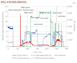
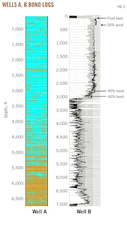
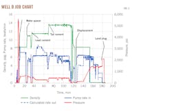
Cementing Well A, the first of the two wells to be cemented, used a reactive spacer (RS) system to combat losses. This reactive spacer system included 20 bbl of water, followed by 20 bbl of a 9.2-lb/gal reactive spacer. An additional 150 bbl of water was pumped ahead of the cement (Fig. 1). This second water stage was intended to act as a nonreactive fluid barrier between the reactive material and the cement and to reduce overall ECD exerted on the weak formations. The bond log showed sufficient isolation above Fox Hills formation.
Well A’s data revealed that a lost circulation event was experienced during the job. Fig. 1 includes a vertical red dashed line indicating the lost circulation event at the 250-min mark. These losses were difficult to see during the job as the only monitoring of the return flow rate was at the shaker screens.
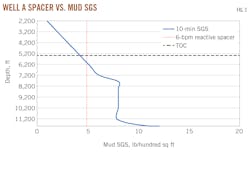
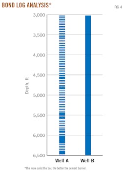
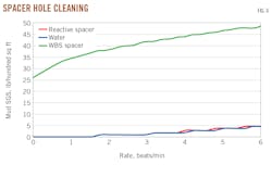
Calculating the return rate showed that lost circulation events caused a decrease in annular fluid velocity sufficient to negatively impact displacement of drilling fluid. Fig. 2 illustrates that at the real displacement rate, the spacer was too thin to effectively clean the wellbore. The result of having this reduced displacement rate can be observed in the bond log and bond log analysis (Figs. 3-4). In Well A, good cement was only found below 5,400 ft and maybe partial isolation from 4,500–5,400 ft.
In an attempt to avoid the Well A losses while cementing Well B, the resulting decrease in annular velocity, and the associated lesser level of mud removal, the operator decided to pump a WBS spacer ahead of the 11.5-lb/gal lead cement (the same density lead cement used for Well A).
The WBS spacer system was selected for use in Well B based on the belief that a reduced flow rate up the annulus, caused by downhole losses during the first job, had decreased displacement efficiency. A small amount of lost circulation material also was added directly into the cement on Well B. Well A had been drilled using a water based drilling-fluid system with a density of 9.4 lb/gal. Well B drilling used an oil-based fluid system at 9.1 lb/gal. Forty barrels of the WBS spacer was mixed at 11.0 lb/gal and pumped ahead of the cement instead of the 9.2 lb/gal reactive spacer system. Both Well A and Well B used 13.5-lb/gal tail-cement density.
The effectiveness of the WBS spacer is evident in the calculated rate-out curves shown in Figs. 1 and 5. In a closed system, the rates in and out should match. During a cement job there are two primary reasons why these rates might not be equal. The most common reason is freefall. Whenever the pipe is loaded with enough cement of substantially higher density than the drilling fluid the cement will start to fall. During the onset of freefall, the return rate is actually greater than the pump rate. This phenomenon can be observed in Fig. 5 between the job times of 42 and 90 min.
Once enough cement reaches the annulus, the freefall volume in the top of the casing starts to back fill. For the next portion of the job, the return rate should be less than the pump rate (90-140 min). From this point on the rates in and out should be equal. If the rate out is less than the rate in and is not from freefall, the mostly likely explanation is a lost circulation event (Fig. 1, vertical red dashed line at 250-min).
A corresponding loss in return rate was not observed in Well B, indicating that the WBS engineered into the spacer system provided the required control (Fig. 5). The WBS spacer system generated the necessary barrier at the wall to resist the additional ECD required for mud displacement and cement placement. An extra 5 lb/bbl of the base concentrate was added to each bbl of spacer, helping mobilize the gelled and dehydrated drilling fluid.
In Fig. 2, for most of the cement interval the mud has a higher gel strength than the spacer’s YP. In Fig. 6, the rheological adjustability of the WBS spacer allowed its YP to be designed substantially higher than what was pumped on Well A. As extra insurance, 20 lb/bbl of an optimized lost circulation material was added to the spacer system in Well B. As an additional contingency plan, a light loading of 1 lb/sack of a particulate lost-circulation material was added to both the lead and tail cements.
To further aid in reducing ECD as the cement was being forced up the annulus, 100 bbl of water was pumped ahead of the WBS spacer system. In Well A, 170 bbl of water had been pumped ahead of the cement job. The accompanying table summarizes the differences between the fluids pumped on the two wells.
The primary difference between these two cement jobs was the addition of the WBS spacer system pumped ahead of the cement on the second well. The resulting bond log showed a much more comprehensive level of isolation in Well B when compared with Well A (Figs. 3-4) and full circulation was achieved throughout Well B’s job (Fig. 5).
References
- Clark, C.R. and Carter, G.L., “Mud Displacement with Cement Slurries,” SPE-4090, Journal of Petroleum Technology, Vol. 25, No. 7, July 1973, www.doi.org/10.2118/4090-PA
- Haut, R.C. and Crook, R.J., “Primary Cementing: The Mud Displacement Process,” SPE-8253, SPE Annual Technical Conference, Las Vegas, Sept. 23-26, 1979, www.doi.org/10.2118/8253-MS
- Smith, T.R. and Ravi, K.M., “Investigation of Drilling Fluid Properties to Maximize Cement Displacement Efficiency,” SPE-22775, SPE Annual Technical Conference, Dallas, Oct. 6-9, 1991, www.doi.org/10.2118/22775-MS
- Guzman, J., Mavares, F., Monasterios, E., and Massirrubi, L., “Casing Centralization and Pipe Movement in Cementing Operations for Improved Displacement Efficiency,” SPE-191255, SPE Trinidad and Tobago Section Energy Resources Conference, Port of Spain, Trinidad and Tobago, June 25-26, 2018, www.doi.org/10.2118/191255-MS
- Smith, T.R., “Cementing Displacement Practices: Application in the Field,” SPE-18617-MS, SPE/IADC Drilling Conference, Feb. 28-Mar. 3, 1989, www.doi.org/10.2118/18617-MS
- Smith, T.R., “Cementing Displacement Practices Field Applications,” SPE-18617-PA, Journal of Petroleum Technology, Vol. 42, No. 5, May 1990, www.doi.org/10.2118/18617-PA
- Calvert, D.G., Webster, W.W., and Lafleur, K.K., “Improved Cementing Operations: A Field Study,” SPE-23987, SPE Permian Basin Oil and Gas Recovery Conference, Midland, Tex., Mar. 18-20, 1992, www.doi.org/10.2118/23987-MS
The authors
Andrew Jordan ([email protected]) is cement technology manager at BJ Services, Tomball, Tex. He has also served as cementing technology director and product line manager at Baker Hughes. He holds a BS degree in mining engineering from Nottingham University (1980) and is a member of the Society of Petroleum Engineers (SPE).
Lucas Albrighton ([email protected]) is product line engineer - cementing at BJ Services, Denver. He has also served as chief technology officer at ALTCem, and a technical advisor at Halliburton. He holds a BS in mechanical engineering from the University of Wyoming (2003). He is a member of SPE.
David Kulakofsky ([email protected]) is global product line manager for cementing and stimulation at Impact Fluid Solutions, Houston. David has also served 30 years as senior global product champion-cementing for Halliburton Services. He holds a degree in chemical & ccean engineering from the University of Rhode Island and Rensselaer Polytechnic Institute and studied master’s level petroleum engineering at the University of Oklahoma. He is a member of SPE, works with API, and is an associate editor for SPE’s Drilling and Completions magazine.
Bryce Ballard is a senior petroleum engineer at Ballard Petroleum, Billings, Mont. He has also served as a petroleum engineer at Crawley Petroleum Corp. He holds a BS in petroleum engineering (2008) from the University of Oklahoma and an MBA from the University of Wyoming. He is a member of SPE.