Phillips 66’s UK plant pioneering refinery carbon capture project
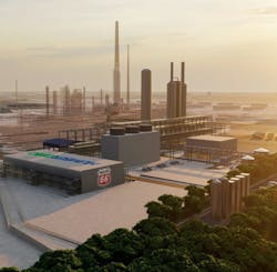
Houston-based Phillips 66 Co. is advancing what could become the first ever industrial-scale carbon capture project to be executed within a refining plant at subsidiary Phillips 66 Ltd.’s 221,000-b/d Humber refinery in the Immingham industrial hub on the south bank of the Humber Estuary, North Lincolnshire, UK, on England’s eastern coast.
Undertaken as part of a more than £1-billion first phase of the UK government-backed Humber Zero decarbonization project the refiner is jointly developing with partner VPI Immingham LLP—a subsidiary of Rotterdam-based Vitol Group that operates an adjacent combined heat and power plant (CHP)—Phillips 66 will leverage proprietary post-combustion carbon capture (PCC) technology from Shell PLC’s Shell Catalysts & Technologies (SC&T) to retrofit one of the refinery’s major processing units. The project also proposes construction of a carbon capture plant on refinery premises to be integrated with the retrofitted unit.
Based on documents released by the partnership July-August 2022, this article provides an overview of the Humber Zero project and related first-phase works proposed for the refinery and CHP. The article also examines the Phillips 66-VPI partnership’s approach to project design and selection of PCC technology and licensors, and presents key lessons the Humber Zero team identified during the process to assist other operators in developing similar decarbonization initiatives.
Humber Zero overview
Humber Zero is a combined set of decarbonization projects designed to lower greenhouse gas (GHG) emissions from the Immingham industrial hub, an integrated complex comprising Phillip 66’s Humber refinery and VPI’s 1.2-Gw CHP, which supplies electricity and steam to the refinery and other nearby industry, as well as electricity to the national grid (Fig. 1).
Under development and coordinated by a joint management team of Phillips 66 and VPI as a platform for demonstrating critical deep-decarbonization technologies on an industrial and commercial scale, Humber Zero’s initial phase focuses on the carbon capture and storage (CCS) components of an industrial decarbonization strategy required to achieve the UK government’s ambition of capturing 20-30 million tonnes/year (tpy) of CO2 by 2030 and more than 50 million tpy by 2035 in hopes of meeting the national net zero target by 2050, while also enabling industry to remain competitive in an increasingly lower-carbon world.
In 2021, UK Research & Innovation—the UK’s the largest public funder of research and innovation through the UK Industrial Decarbonization Challenge—awarded match funding of £12.5 million to Phillips 66 and VPI to develop conceptual and front-end engineering and design (FEED) for the initial £25-million phase of Humber Zero projects that, together, target carbon capture starting in 2026 to reach a rate of 3.8 million tpy by 2027. Worley Ltd. won the FEED contracts and expects to complete its work for the CHP by third-quarter 2023 and for the refinery by yearend 2023.
This first suite of projects will involve retrofitting SC&T’s Cansolv CO2 post-combustion carbon capture (PCC) technology to existing equipment where gases produced from combustion are emitted. These units include the Humber refinery’s fluid catalytic cracking (FCC) unit and two combined-cycle gas turbine (CCGT) trains as well as two auxiliary boiler stacks at VPI’s CHP (Fig. 2). The proposed projects also will include construction of carbon capture plants at each of the sites, both of which will be integrated with the retrofitted units (Fig. 3). Scheduled for start of construction in 2023, these projects, once completed, will result in 500,000 tpy of abated CO2 emissions from the refinery and 3.3 million tpy from the CHP.

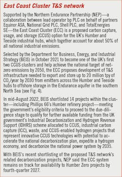
Located within a small geographic area and housing several critical industries that together account for 40% of UK industrial emissions, the Immingham hub’s proximity to the nearby port provide Humber Zero’s proposed projects access to two CO2 transportation and storage (T&S) networks under separate development by Harbour Energy PLC and Northern Endurance Partnership, respectively (OGJ Online, May 13, 2022; Oct. 14, 2021; Fig. 4; see accompanying box). Following capture, these T&S networks will deliver CO2 from Humber Zero via pipeline for permanent storage in North Sea offshore saline aquifers and depleted oil and gas fields.

Fig. 5 shows a map of the Humber industrial region and proposed T&S networks for exporting Humber Zero’s captured CO2 to offshore storage.
A future phase of Humber Zero aims to produce hydrogen at scale—both for immediate use as well as fuel switching from natural gas to hydrogen—to further decarbonize the Immingham industrial site and meet Humber Zero’s long-term goal of transforming it into a CCS and hydrogen hub equipped to provide cost-effective decarbonized energy supply and storage opportunities to surrounding industry by 2040.

Once fully executed, the broader £1.2-billion Humber Zero program would reduce overall CO2 emissions from the Humber region by as much as 8 million tpy by 2030. In addition to creating 2,500 jobs during construction and 200 permanent jobs upon completion, the fully realized project would safeguard 20,000 existing jobs, all while delivering necessary infrastructure to support continued economic growth for the region in a future green economy, Phillips 66 and VPI said.
Early development
Designed to ready the refinery and CHP for PCC—a process that involves treating flue gas after combustion has taken place and occurs at near-ambient conditions— common parts of Humber Zero’s first-phase projects for the refinery and CHP were developed during preliminary FEED (pre-FEED) and initial front-end loading (FEL-1) stages with support from Wood PLC, which also acted as integration project management contractor.
The Humber Zero partnership and Wood established a process at the start of pre-FEED and FEL-1 that included a technology shortlisting exercise implemented before technology providers were solicited to submit proposals for the CO2-capture units. Licensor evaluation procedures and tools were developed covering everything from technical query clarifications, criteria weightings, equipment list normalization, capital expenditure estimation, and economic modelling.
The journey from conceptual design basis to PCC technology selection entailed accurately assessing and characterizing flue gases from the refinery’s FCC and the CHP’s CCGTs and aux-boilers to help identify pretreatment requirements for the proposed PCC projects.
Key activities executed during pre-FEED and FEL-1 included:
- Conducting initial safety reviews and siting studies.
- Reviewing key utility and energy requirements.
- Commencing ecological surveys, appointing an environmental contractor, and establishing strategies for planning and permitting.
- Establishing the basis of design, including the need for pretreating flue gases to remove contaminants before entrance into a future PCC plant, an especially important step for the refinery’s FCC flue-gas stream.
- Review and selection of available carbon capture technologies and appointment of associated licensors.
As established by pre-FEED and FEL-1 works, one of the partnership’s key requirements for proposed PCC units at the refinery and CHP was that they be able to achieve a minimum CO2-recovery efficiency of 95% from FCC, CCGT, and auxiliary boiler flue gases.
Technology selection process
Most CO2-capture technologies use solvents to selectively remove CO2 from gas mixtures. After regeneration via heating to release pure CO2, the solvent is reused within the process in a continuous loop.
The following section provides an overview of PCC technology employing an amine solvent-based process to remove CO2 from the flue gas in an absorber tower, with subsequent capture of CO2 from a regeneration tower (Fig. 6). The amine solvent-based PCC process described mirrors the SC&T Cansolv CO2-capture system that will be adapted for retrofitting units at the refinery and CHP as part of the Phillips 66-VPI partnership’s first-phase Humber Zero projects.
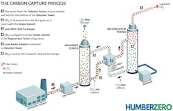
The main process steps within a typical amine solvent-based carbon capture process involve:
- Gas pretreatment, including a flue gas blower and cooler.
- CO2 absorption with water washing.
- Solvent regeneration.
A PCC plant also could include installations for:
- Fresh solvent storage and makeup.
- Solvent reclamation.
- Effluent treatment.
- CO2 compression, dehydration, and metering for export.
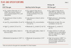
Gas Pretreatment. Since the flue-gas feed to the PCC unit is hot and contains contaminants such as dust, SOx, and NOx, it must be cooled before reaching the CO2 absorber to achieve high recoveries and mitigate solvent degradation.
The pretreatment technology choice depends on the level of contaminants in the flue gas.
While flue gases from VPI’s CCGTs and aux-boilers do not require additional pretreatment other than quenching in a direct-contact cooler, flue gas from the Humber refinery’s FCC contains contaminants above acceptable levels for the carbon capture plant. Licensors usually will stipulate additional equipment such as a wet-gas scrubber or a wet electrostatic precipitator to minimize solvent degradation and aerosol generation.
Cooling achieved by direct contact can condense much of the combustion water present in the flue gas to remove contaminants such as dust and SOx. Additional equipment for caustic dosing and solids-handling may be required to enable these processes.
Condensed water from the flue gas is purged continuously and either sent to effluent treatment or reused if suitable as make-up cooling water.
Flue-gas blower. Because post-combustion flue gas streams typically are near atmospheric pressure, a flue-gas blower is needed to provide the motive force to overcome any pressure drop across the pretreatment section and CO2 absorber. If sufficient pressure is available from the emissions source, a blower may not be required, eliminating the need for a major rotating equipment item.
Fan size will be smaller if the blower is in the cool gas stream downstream of the pretreatment section. This decision, however, is governed by the arrangement and construction of other parts of the PCC unit, as it may be impractical to install the blower downstream of pretreatment.
CO2 absorption. Typically, the CO2 absorber is a cylindrical steel column, with rectangular concrete columns used for higher flue-gas flowrates. The column normally contains structured packing, with the CO2-absorption section at the bottom and water-wash sections at the top.
Cooled flue gas is introduced to the column’s bottom to make contact with solvent fed from the top of the absorption section. CO2 in the flue gas is absorbed by the solvent. The CO2-rich solvent is then sent to the regenerator column.
Since the temperature rise resulting from exothermic reactions within the CO2 absorber reduces the lean-solvent absorption efficiency and increases the amine-degradation rate, the semi-rich solvent at the bottom of the CO2 absorber is often drawn off, cooled, and pumped around.
Wash water. To minimize solvent atmospheric losses and emissions, the CO2 absorber includes one or more water-wash sections. The flue gas—now with CO2 mostly removed—flows upward into the water-wash section, which contains a circulation of wash water and can incorporate a cooling system to cool flue gas it contacts, removing the heat of absorption and washing out any entrained solvent.
A demister minimizers solvent loss from the top of the wash section, while treated flue gas from the top of the absorber is emitted into the atmosphere.
Solvent regeneration, storage, and makeup. Rich solvent from the bottom of the CO2 absorber is preheated against hot lean-solvent circulation in the lean-rich solvent heat exchanger before moving to the top of the regenerator. If the regenerator is a cylindrical column with structured packing, the gas-liquid distribution increases.
Low-pressure steam is supplied to the regenerator reboiler for heating the solvent to high temperature and stripping out CO2. After regeneration, the lean solvent is recycled back to the CO2 absorber via the lean-rich heat exchanger.
Energy efficiency is improved around the bottom of the regenerator by implementing additional heat integration or, in some cases, novel proprietary techniques.
CO2 with water vapor at the overhead of the regenerator is cooled by the regenerator reflux cooling system consisting of the regenerator reflux cooler, reflux drum, and reflux pump. The steam condensate from the regenerator reboiler is recovered and returned to the steam-condensate system. Recovered CO2 product is then sent to the CO2 capture unit battery limits for further treatment and compression. The unit includes a solvent-drainage and make-up system that includes a solvent storage tank, solvent sump, solvent-sump pumps, and filter.
During maintenance and inspections, the solvent-storage and make-up systems are used for draining solvent from process equipment. Since solvent usually will not oxidize under cold draining conditions, nitrogen blanketing is not required.
Solvent reclaiming. The primary purpose of reclaiming is to remove soluble solvent-degradation products such as heat-stable salts, dissolved metals, and suspended solids accumulated in the solvent. Different technologies are used to achieve reclaiming, including proprietary filtration methods and thermal vaporization of the solvent to leave in contaminants.
Waste from this process is removed as slurry into a tank for periodic truck disposal, while recovered water and solvent are returned to the main circulation.
Effluent treatment. To minimize the load on existing treatment installations, water from the quencher and wet-gas scrubbing (WGS) system must first be treated to remove accumulated dust and other contaminants. Wastewater and solids-handling systems—which can include mixing tanks, clarifiers, filters, filter cake bins, conveyors, aeration tanks, blowers, sumps—are therefore integral to the flue-gas pretreatment system. Separated solids from this stage would be sent via truck for offsite disposal, while water can be sent to the wastewater treatment system.
Design basis
The Humber Zero team determined flue-gas specifications for Phillips 66’s FCC and VPI’s CCGTs and aux-boilers during pre-FEED and FEL-1, helping establish the degree of pretreatment required and heat recovery available upstream of PCC plants planned for the operators’ individual projects.
Table 1 details flue-gas specifications for the respective units.
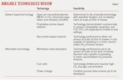
Available technologies review
The Humber Zero pre-FEED team reviewed available carbon capture technologies to determine which would be suitable for the Humber Zero project. This review was carried out at a time during the pre-FEED phase suitable to help inform the technology selection process and narrow down technologies for more detailed consideration as the selection process progressed.
The review—which considered specific needs of the industrial participants and applications for Humber Zero—is a case-specific suitability assessment and not intended to be a broadly applicable evaluation of available technologies. Proven technology readiness and scalability in similar applications as well as economic viability of the technology were key considerations.
Review results showed the only PCC technology proven at a comparable commercial scale to achieve the carbon capture target of Humber Zero first-phase projects was SC&T’s proprietary amine-based solvent Cansolv CO2 capture process (Table 2). The Humber Zero team, however, plans to keep development of the carbon capture technologies under review for potential future applications by Humber Zero project participants.
Energy input
Amine solvent-based CO2 capture technologies are inherently energy intensive, resulting in allocation of most operating costs to steam and power consumption.
Some of the largest power-consuming plants involved in the CO2 capture process—excluding pretreatment and post-treatment compression—are the cooling system and flue-gas blower. The selected process for Humber Zero’s first-phase projects enable high efficiency in the CO2 absorber as well as mitigate solvent degradation. Depending on availability of cooling media and plot space, the cooling system can be direct-air, evaporative-water cooling, or a hybrid of the two. The process’s large duty requirement is reflected in large power demands for air-cooler fan motors or cooling-water pumps.
The largest steam consumer in the capture process is the solvent-regeneration column reboiler in the CO2-recovery section. The solvent-reclamation and polishing section also consumes a lot of the unit’s low-pressure steam. Combined, these two processes account for the bulk of process heat duty and, therefore, steam consumption.
Licensors can provide heat integration and other proprietary techniques to recover heat from the bottom of the regenerator column, helping reduce low-pressure steam demand and improve overall energy efficiency.
Scale-up
Since scale-up is an important consideration when reviewing carbon capture technology, licensor references—particularly operating plants and the track-record availability of PCC units—is key to determining risks associated with a given technology.
Capacities of the planned Phillips 66’s FCC PCC unit and VPI’s aux-boiler PCC unit were both found to be well within the demonstrated capacity of commercially operating units. Scale-up of the selected technology is therefore considered less of a concern for these Humber Zero first-phase projects.
For VPI’s CCGT application, CO2 content of the flue-gas source was low relative to total flue-gas throughput. Although the CO2 capacity (based on the amount recovered) was within proven limits, the Humber Zero team determined total flue gas volumes exceeded current scale. This required licensors to provide evidence—based on previous experience and lessons learned on similar projects—that they were equipped to manage potential risks of scale-up for the CHP project.
While some licensors scale up using a building-block methodology (e.g., expanding capacity by increasing the number of incremental capital investment and capacity additions to match project objectives), others simply increase the size of process equipment. The credibility and constructability of both methods should be closely reviewed when considering PCC unit design.
It is also worth noting that, based on cost and constructability, a design break point above 1 million tpy of CO2 exists, which some licensors may switch from conventional circular-type quench or CO2 absorber column to a square or rectangular design. This should also be reviewed to assess possible impacts on available plot space and potential construction issues.
Permitting considerations
Implementation of a PCC plant likely will require a planning and permit application to relevant local and regional authorities, including environmental regulators. Use of the solvent in the selected process could result in emissions (e.g., amine, amine-degradation products), which will require submission of a detailed environmental impact assessment (EIA) as part of these applications.
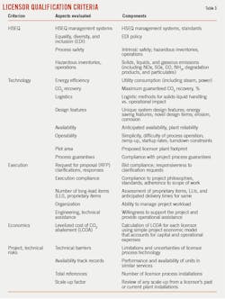
Licensor qualification
A Humber Zero licensor qualification process was completed to shortlist viable technology providers capable of delivering project requirements. Licensors submitted proposals, which were evaluated using the following criteria:
- Technology commercially available to support design phases through to planned mid-2020s startup.
- Previous experience providing a design package and process data to support the design phase.
- Previous delivery of a project design at a similar throughput rate.
- Deployment of the technology in operating or demonstration plants with capacities of more than 50,000 tpy.
- Track record as a provider of gas-treating units under license.
- Experience in facing adverse reliability issues and the ability to bring forward lessons learned from the experience.
- Willingness to participate in and provide information regarding the project, including supporting knowledge transfer.
Licensors identified and shortlisted as capable of handling the first-phase PCC projects by the qualification process were invited to submit separate bids for the VPI and Phillips 66 Humber Zero work.
Licensor evaluation
The Humber Zero team evaluated submitted bid proposals from licensors using criteria covering health, safety, environment, quality (HSEQ); technology; execution; economics; and potential risks based on past project experience and technical barriers (Table 3).
Assessed and evaluated for completeness, quality, technical, and economic performance for the appropriate VPI and Phillips 66 project scope, bids also were subject to a rigorous normalization review to ensure all were evaluated and costed on a consistent and fair basis.
Table 4 includes examples of project-licensor normalization.

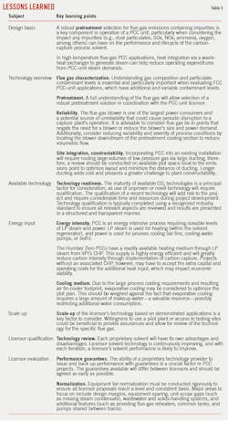
Lessons learned
Lessons learned by the Humber Zero team over the course of developing and executing the process to select the most appropriate project technology, as well as qualify, evaluate, and appoint licensors for the Phillips 66 and VPI projects, are applicable across a broad range of sectors seeking to decarbonize operations via PCC.
Working alongside SC&T and Worley, Phillips 66’s novel retrofit of the Humber refinery’s FCC unit with Cansolv CO2 technology to prepare for integration with the site’s proposed PCC plant marks development of technology and demonstrated project experience that can potentially help decarbonize the more than 300 FCC units currently operating globally, said Darren Cunningham, Phillips 66’s lead UK executive and Humber refinery general manager.
Table 5 presents key learnings the Humber Zero team identified during technology and licensor selection in the pre-FEED and FEL-1 stages of developing the first-phase decarbonization projects for the refinery and CHP.
Next steps
With the refinery and CHP projects now in their FEED and FEL-2 phases, the Humber Zero team—including engineering and environmental partners—will focus on the following:
- Conducting the EIA and submitting planning and permitting applications.
- Maturing the engineering design and updating the cost estimate to aid final investment decision (FID).
- Preparing a FEED package and scope of work for engineering, procurement, and construction (EPC) tendering.
Phillips 66 also plans to execute a FEL-3 stage before taking FID and awarding EPC for the refinery’s Humber Zero first-phase PCC decarbonization project.
About the Author

Robert Brelsford
Downstream Editor
Robert Brelsford joined Oil & Gas Journal in October 2013 as downstream technology editor after 8 years as a crude oil price and news reporter on spot crude transactions at the US Gulf Coast, West Coast, Canadian, and Latin American markets. He holds a BA (2000) in English from Rice University and an MS (2003) in education and social policy from Northwestern University.